All Activity
- Past hour
-
@Dunkin Did you find the correct template?
-
Minor thought process here and wanted to see if anyone has tried this. I have a negative battery terminal disconnect, and when used, obviously, the clock stops. I was thinking of keeping the power to the instrument for illumination of the clock face, but to get the mechanism (minute and hour hands) to run off a button battery. Stupid idea? Why didn't I think of that? Comments/Suggestions/Thoughts always welcomed.
-
I literally just found this in another post of yours. Thanks for the resource!
- Today
-
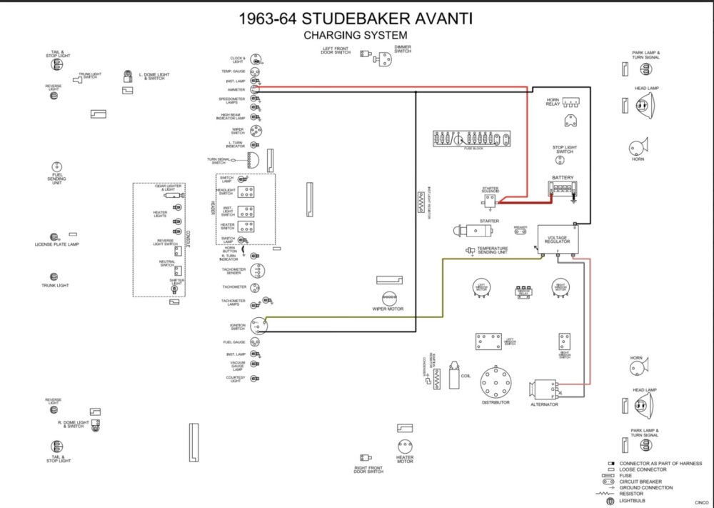
This is a colorized version that has the different system's separated. Scroll down to the 63-64 Avanti. https://drive.google.com/drive/folders/1eSSmIKiSS8lzc9kPYRm4Uk3yeu72TIlj This is a link to a post from a SDC member on the SDC message board. Steve.
-
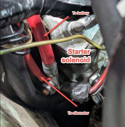
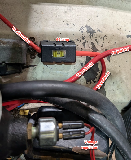
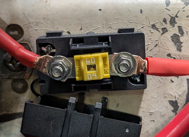
Final Assessment I've completed the install of the new alternator from Bob at AvantiParts.biz. I believe it's a Remy 55-amp. It fit fine. I couldn't get the battery to charge by hooking up the alternator's BAT to the voltage regulator. I was perplexed because the car was running so much better at idle. It must have just been running off the fully charged battery that I was topping off nightly. But if the new alternator wasn't giving the battery 14.xx volts, then was the original alternator bad? Or was/is the voltage regulator bad? I ended up taking 14' of 8awg from the alternator's BAT to the battery side of the starter solenoid instead of going to the voltage regulator, with an inline 60amp fuse. However, the regulator is working enough so that the dashboard amp-meter still works (it moves back and forth when the blinker is on), as does the key-on 12v supply to the alternator. Thanks for all the help with this, my first major project on this fun to drive car. As always, any comments/suggestions/ideas are still welcomed.
-
@A0136 Steve. That's diagram is much easier to read. What's the source?
-
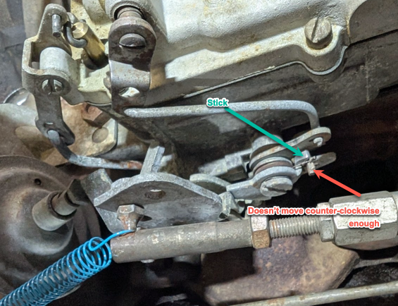
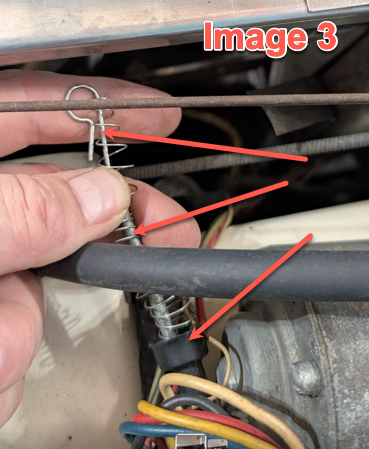
Excuse the newbie question, I haven't had a carburetor in 25+ years and I always hated working on whatever AMC used. The choke valve on my carb doesn't close enough to start a cold engine. I've tried different ways to try and set it with the gas pedal to no avail. I also think it, at times, doesn't open enough with a warm engine. I hit the linkages and anything that moves with carb cleaner than on the outside hit the linkages with PTE Teflon spray. That's not the cause. I believe it is the trip lever and/or the fast idle cam. It seems as if the trip lever doesn't move freely (should it?). When I force it with my fingers, it will move, then the butterfly will close enough to start. Comments/Suggestions/Ideas? The second and third pictures show a spring that is not connected to anything that I noticed when working on the alternator and was going to ask about in a different thread, but I'm including it here just in case it's carb related.
- Yesterday
-
Sometime in the 80s my grandfather put in a third brake light. It was hooked up to the rear left and right leads to the bulbs. There was a module attached that would figure out if the lights were flashing (turn signal) and keep the brake light steady on. I just converted it to an LED mainly because it was in the way of the tiny rearview mirror. I realize it's not hazard lights, but if it triggers an idea...
-
@Gunslinger thanks for that tidbit of info. Yes the entire braking system was replaced and it uses DOT 5. I did a bit of research, well, I had AI search for me and compile an answer from sources. I'll Have to next research 1). How to convert to a mechanical switch, and until then, 2). Find a replacement hydraulic switch. 1. Corrosion and Electrical Arcing (The Most Likely Cause) The primary theory, which is backed by inspection of failed switches, involves the non-hygroscopic nature of DOT 5 fluid interacting with the internal electrical contacts: Water Pooling: DOT 5 (silicone-based) does not absorb water (it is non-hygroscopic), unlike DOT 3 or DOT 4 (glycol-based). Any moisture that enters your system (which is unavoidable, even with a sealed system) remains as a separate droplet. This water tends to sink to the lowest point, which can be the caliper, or, critically, the sensitive chamber of the brake light switch. Corrosion: This pooling of water causes localized corrosion on the internal metal contacts of the switch. The Switch Design Flaw: The vintage hydraulic switches (like the one on your Avanti) are not "snap-action." The contacts close slowly as pressure builds. This slow closing action causes arcing across the contacts. In the presence of the silicone fluid and the localized moisture/corrosion, this arcing creates a thin layer of non-conductive carbonization or corrosion that prevents the circuit from closing reliably. This is why you have to press harder and farther—you need more pressure to physically push through the layer of crud on the contacts. 2. Viscosity and Compressibility Soft Pedal: Silicone fluid is slightly more compressible than glycol fluids (DOT 3/4). While negligible in hard braking, it can create a slightly spongier pedal feel. Activation Threshold: Due to the soft feeling, some enthusiasts report that it takes a higher initial line pressure to overcome the switch's internal spring/diaphragm to activate the light, causing the exact symptom you are experiencing. What to Do About It If your Avanti currently has DOT 5 fluid, you are faced with a choice: Replace the Switch Seasonally: Many classic car owners running DOT 5 are aware of this issue and simply replace the cheap hydraulic brake light switch every year or two as part of their maintenance schedule. Convert to Mechanical Switch: The most reliable solution, which many Avanti owners resort to, is to remove the hydraulic switch entirely (and plug the master cylinder port) and install a modern, adjustable mechanical brake light switch on the brake pedal arm under the dash. This is the most popular permanent fix for this decades-old issue. Full Fluid Conversion: Converting back to DOT 3 or DOT 4 is a massive undertaking. The silicone fluid permeates the rubber components, and mixing the two types causes a gummy sludge. To switch back, you would need to completely replace all rubber components (hoses, seals, wheel cylinder cups) and meticulously flush all metal lines, which is often prohibitively expensive and difficult.
-
I purchased a gold ‘S’ repo hood emblem years ago that also faded from sunlight…. I was lucky to find a nice used original emblem at South Bend meet with gold ‘S’ that seems to be retaining its vibrant gold color.
-
To each his own, but I think the emblems add to the looks. Mike
-
Dobb This is easier to read than the shop manual version. Power from the alt. Goes to the regulator and then thru the amp meter before going to the battery, so check those connections and for continuity thru the amp meter also. Steve.
-
 DobbM changed their profile photo
 -
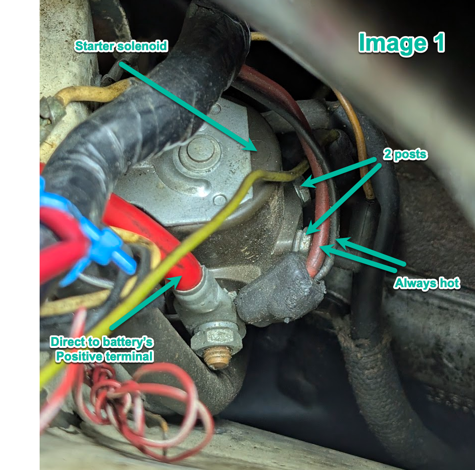
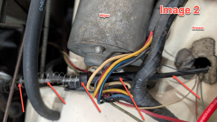
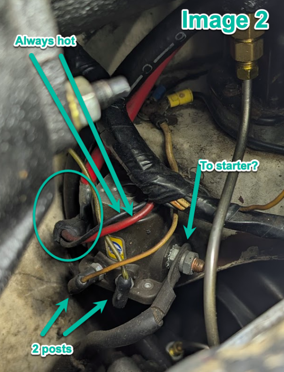
(Manual arriving Monday) I believe this is the starter solenoid. There are 2 posts that have a smaller gauge wire attached to them (Image 2). One of them is should be key-on hot, correct? They both disappear into the harness. Still looking for a source to have key-on 12v power for the alternator. Per the above referenced article: "The “IG” terminal needs a wire connected to it that is hot with the key turned to the ON position. Moving the white with black stripe wire from the FLD connector to the IGN lug on the voltage regulator will provide that." Since this is not providing any voltage to the alternator is why I believe that the external regulator is bad. Thank you.

-

Brake pedal goes almost to the floor before brakes engage
Adam DeRosa replied to Jim S's topic in 1965-83 Avanti
Jim - glad you got the problem with your brakes solved. In 1972 your car originally came with breaker points distributor, with power to the coil supplied by the Pink (with black stripe) resistance wire once running. During Start, full voltage was supplied to the coil by a Yellow by-pass wire that ran from the starter solenoid to the coil. With HEI ignition, you need full voltage to the coil all the time. You'll need to replace the Pink resistance wire. It should run to a connector on the steering column which you can get to if you crawl under the dashboard. You can then remove the resistance wire at the connector and run a new wire to the HEI system. - Last week
-

'63 R1 Alternator Replacement - and final synopsis
Gunslinger replied to DobbM's topic in 1963-64 Avanti
Engine running the system should be charging at 13.8 volts. -
Engine running, and the battery is registering about 12.6v (same as with car off, key-off). Also used the multimeter to test the 12v key-on power and nothing. Where's a good place to get the key-on power? There are 4 terminals on the external regulator, three go to the original alternator, one of which is supposed to be key-on power. Is it feed power from the battery side of the starter? Just looking for a clean way to grab that key-on power. Thanks.
-
I'm late to the game, but added the emblems to my 1980, both hood and sail panel. I like it. I bought the gold "S" buckles, but they quickly faded to silver. Disappointing, but they still look good. I also added the 63/64 wheel covers and plan to remove the front spring shims.
-
Do you have a voltmeter?… That would identify how much current and where it is going… or not going…. Even a basic 12V test lamp will allow you to ‘see’ the electricity.
-
Ok, I installed the new alternator and the car is running much better. However, the battery is not being charged by the alternator. Also, the ignition powered wire isn't delivering 12v. My only assumption is that the external regulator is actually bad. I rewired according to the above referenced article by Bill Henderson. Next step is to wire the BAT alternator terminal directly to the the battery, with inline 60amp fuse, and just bypass the regulator entirely. My next question is how to get 12v to the alternator when the ignition key is "on"? (My shop manual is in the mail and should be here Monday.) Thank you everyone.
-

How many Avantis are still in existence?
ronmanfredi replied to Ronny Daytona's topic in Avanti Trivia
I'm going to see if we still have any control over the site and possibly bring it to life again. -
In addition… no extra holes to drill!..… The factory screw which retains console side upholstery can be utilized to support toggle switch by crafting simple ‘L’ shaped bracket.
-
That’s it… I have an ‘off-on’ toggle mounted on driver’s side console within easy reach. The lockup disconnect at rear of stop light switch is still functioning. My normal driving routine is to not lock the converter unless I’m on the highway, or higher speed secondary road. As I remember, the problem I found with the factory computer controlled converter lockup was that it locked to early… at too low an engine RPM causing what I can best describe as ‘lugging’. I heard many years ago that not allowing the converter to lock up automatically would damage the converter by overheating it…. In 15 years of manually controlled lockup, overheating has never happened… ALSO…. I believe the simplest way to accomplish this, if your Avanti has CCC, is to install toggle into the converter lockup switch wiring (at rear portion of stoplight switch)….located at brake pedal.
-
-
Ha!
-
The hydraulic brake switches suffer from a dual problem beyond aversion to silicone fluid…current ones are made offshore now and simply don’t last…and original, well made switches are old enough now that they’re suspect in how well they work for any length of time.