


WayneC
-
Posts
541 -
Joined
-
Last visited
Content Type
Profiles
Forums
Events
Posts posted by WayneC
-
-
In my records I have these rear brake cylinders listed as correct for Avanti, at much lower prices (do a Google search on them).
Wagner F37782 & F37783
I believe I've used them in the past on Avanti's (I've owned a half-dozen) but its been quite a few years since I've changed any rear cylinders.
They are listed as having 13/16" bores, but I never noticed any braking issues with them.
...Rockauto.com lists them for $11.26 each and I think I've even purchased them on Amazon, although there are none there at present.
Used on '67 & '68 Mustang, and probably many other cars
Another alternative is to have your old cylinders re-sleeved, at a cost of about $50 each plus shipping.
http://www.applehydraulics.com/brakes.htm
-
RQB3263 This web site might help you get it right when changing wheel ans tire sizes...it did me ...avoid costly mistakes...
<www.calculation.com/calculator/tire-size.php>
Seems to be a bad link, perhaps this is it: https://tiresize.com/calculator/
Here's one I like: http://www.rimsntires.com/specspro.jsp
-
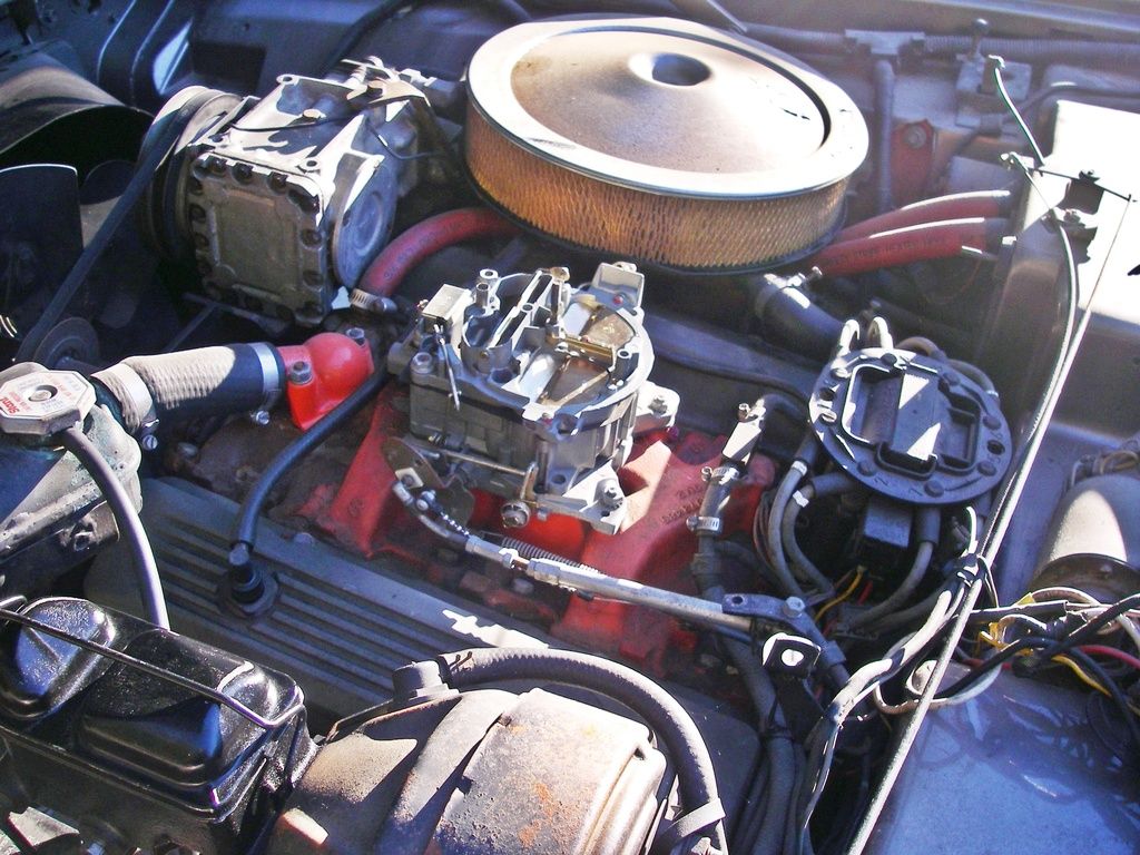
If any of you have a 1970-72 Avanti II, take a look at the attached photo. Does your air cleaner look like this? This is what is on my 1971 Avanti II. It is a dual-snorkel are cleaner with a chrome top.
Is your air cleaner black with a chrome top? Is (was) there a decal on the chrome top? What did it read?
I have read that the pictured air filter was used on Corvettes in 1970. My goal is to match how the car was originally delivered in 1971.
Thank you in advance!
Here is a poor picture of the one that came on my 1971 Avanti (a/c removed and slid/pivoted to one side) which I bought in about 1979; I have no reason to think the prior owner changed the air cleaner as the car appeared bone stock at the time. I can get better pictures if you'd like.
http://i1032.photobucket.com/albums/a408/waynecpb/IMGP0048%20edited_zpsv2rhaz7x.jpg
-
I don't think Avanti used any specially-formulated paints, and in fact the customer usually specified the color, usually something being used on other American cars. In fact, a quick Google search says there was a color called "Meridian Turquoise" used on 1968 Pontiacs (and possibly other GM cars), although that looks more blue than green. It should be possible to order a small touch-up spray container of the colors you find from web vendors, to verify the color you want; also, automotive paint stores often have old paint chip books you can peruse.
http://www.autocolorlibrary.com/aclchip.aspx?image=1968-Pontiac-pg01.jpg
But, you are not likely to find a shop that will spray lacquer paint anymore, the EPA has pretty much stopped that, and even finding lacquer paint is near-impossible; chances are you'll have to use a one-part enamel or a base-coat/clear-coat system. So, paint-matching by the paint shop is the most likely solution, anyway.
http://www.paintforcars.com/blog/the-beginners-guide-to-choosing-automotive-paint/
-
,
on a 350 SBC. I want to remove it, but there are 2 sizes.
I can't answer directly, but most 350ci engines take the 2" valve, so that's most likely.
Since you already know your exhaust pipe is 2", a larger heat riser bore would do nothing for performance anyway.
The risers are available from most parts stores (check your local ones), so you could remove the old one
and measure the bore and then drive to the parts store to get the replacement... they may even let you
take both sizes in advance and bring back the one you don't use.
-
So, did you not follow Bob's (Avanti83) advice that you should use relays and run the H4 bulbs directly off the battery rather than plug them into the old circuits?
-
I'd say the chances are just about zero if you really mean 8-track... 8-track players were large units, mounted by the factory beside the console on the passenger side.
There were some period cassette player radios that can fit. I am not at home today to check and my memory is bad, but my 1980 Avanti came with a (Blaupunkt?) radio/cassette player...I believe the radio station indicator face swings inward to allow the cassette to enter; may have required a slight modification of the original Stude rectangular hole, but very minor.
This might be a better approach: http://www.instructables.com/id/Bluetooth-Upgrade-Your-Old-Car-V2/
(haven't researched it to see if it's feasible for the Avanti radio, but it may be)
-
I am not at home to check, but I think the Stude Avanti shop manual should have a procedure for that.
Do a search of this website using the search field to the upper right of the page... click "this topic", choose "Forums", and type "radio removal" in the search field before clicking the magnifying glass.
Here is a link to some instructions:
https://www.studebakerparts.com/studebakerparts/store/s/html/pages/avantiam-fm.html
Here is another approach to adding a modern sound system:
http://www.crutchfield.com/S-1BdUwWYqx0l/learn/customcar/showroom/BillH_Avanti.html
I replaced an original radio, but it was so long ago I've forgotten how I did it... my suspicion is that I was able to remove the unit by pulling one end through the speaker cut-out atop the dash, but that I had to uncover the right side of the console to get my arm up to maneuver the radio, and that I shaved the edges of the speaker opening somewhat to accomplish it, (cuts covered by the speaker grill outer perimeter)... but, my memory may be failing me. I do know it wasn't easy! I think I still have that radio.
Hopefully someone who has done it recently (or has a better memory) will chime in here.
-
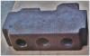
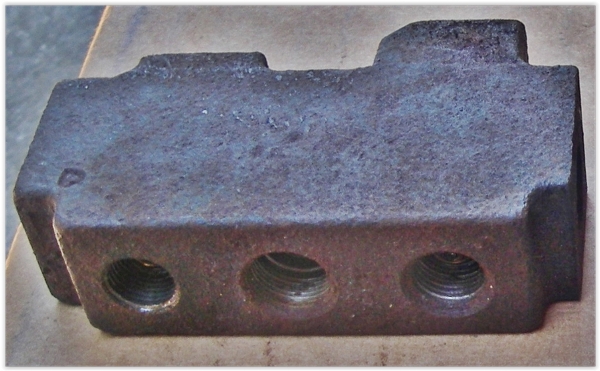
I would like to replace the brake distribution block on my '71 Avanti. It hangs on a bracket just beneath the master cylinder.
It doesn't appear to do much except provide a warning light if either the front brakes or the rear brakes lose pressure (hydraulic leak)
Mine has become very corroded, and I'm pretty certain the warning light switch does not function. When I tried to remove that switch, it fell apart.
I checked Stude Intl catalog and did not find it listed; haven't tried any other vendors as yet.
I did a lot of searching, and came up with a distribution block used on 1967 to 1969 Camaros that looked like a dead ringer for mine.
No other manufacturers seemed to have one that appeared even close to mine.
I ordered it. But, on looking closer when I went to install it, I found that the Camaro block has an extra hole in the back (that side was not shown in the photos I saw).
Not a big issue, that outlet can be blocked off.
But, the outlet hole for the brake line going to the rear cylinders was almost imperceptably smaller so the line to the rear brakes cannot be connected.
That's a show stopper. Even if I bend lines and do some sort of adapter pipe, my fear is the size differential could affect braking balance between front & rear.
Anyone know where to get the correct block?
-
Try W-I-L-D-F-E-L-R, second from last letter is an L not i
Ahh, of course. Thanks!
-
Bill, I am interested in photos, but I am unable to email you, please send them to the address I listed in post #13.
Actually I had tried copper.net first (twice), then tried cooper.net thinking perhaps you made a typo, but I had errors on both copper and cooper... I inadvertently posted the cooper error message.
So I tried again today and got the same error (don't ask me to explain it, it's above my pay grade... perhaps an issue between my email provider and your email provider):
"This message was created automatically by mail delivery software.
A message that you sent could not be delivered to one or more of its recipients. This is a permanent error.
wildfeir@copper.net INVALID_ADDRESS, ERROR_CODE :550, ERROR_CODE :Recipient Rejected: No account by that name hereReceived:from [10.0.1.9] (ip98-185-215-160.sb.sd.cox.net [98.185.215.160]) by mx.zohomail.com
with SMTPS id 1466352291445689.6189861143637; Sun, 19 Jun 2016 09:04:51 -0700 (PDT)
Message-ID:<5d3b46ee-e6b2-12b1-4eea-ecf2d6a2138a@jagsnvettes.com>
Date:Sun, 19 Jun 2016 09:04:14 -0700" -
Interesting discussion, appreciate the photos. Does not look like an easy job.
I have a couple of questions regarding the photo of the cut-off rear portion (extension) of the cowcatcher in place...
- the holes in the side of the cowcatcher don't line up with holes in the frame, I assume the radiator support needs to be jacked-up a bit to raise the body to be able to line up the holes?
- There appear to be what look like rivet heads on the surface of the cow-catcher extension on either side of the "long through-bolt"... are they rivets, and if so, what are they holding?
Wildfeir: in your post #4 above you offer photos, but your email address isn't working, my emails are returned saying "no such address" (see below); please send them to me waynec@jagsnvettes.com
************************************************************************************************************************************
This message was created automatically by mail delivery software.
A message that you sent could not be delivered to one or more of its recipients. This is a permanent error.
wildfeir@cooper.net INVALID_ADDRESS, ERROR_CODE :550, ERROR_CODE :no such address
Received:from [10.0.1.9] (ip98-185-215-160.sb.sd.cox.net [98.185.215.160]) by mx.zohomail.com
with SMTPS id 1466272167427681.3713209870551; Sat, 18 Jun 2016 10:49:27 -0700 (PDT)
Message-ID:<ef63e173-814e-0e60-4aea-851d5ee3f4ac@jagsnvettes.com>
Date:Sat, 18 Jun 2016 10:48:53 -0700**************************************************************************************************************************************
-
That loose end should be stopped by a pin protruding from the valve body.
Maybe this picture will help: http://www.summitracing.com/parts/oer-3887023/overview/make/chevrolet/model/chevy-ii
You could always install a new one... you'd need to determine the manifold opening diameter (likely either 2" or 2.5") and match it...
http://www.ebay.tv/sch/eBay-Motors-/6000/i.html?_sop=22&_nkw=heat+riser+valve&_frs=1
-
Stude used 18 gauge from ign sw to ign terminal on the voltage regulator (yellow with black trailer)
-
I may be thinking about this wrong, but there should be no hot wire to the door switch. There should be a ground wire and a wire that carries that ground to the lamp when the switch connects. The only reason you are reading that wire as hot is because the circuit is open, the switch is not activated, the voltage is passing through the bulb because it is an open circuit.
Am I thinking about this wrong?
I think you have it right, except for terminology.... voltage passes through the courtesy light bulb when the circuit is "closed" ("open" circuit means there is no circuit). The door switches only control a single courtesy light (not the side "dome" lights), and they control it by providing (or not providing) a ground connection... circuit is open when BOTH doors are shut, circuit is closed (completed) when either door is open.
I mentioned in my prior post that some time ago I had made an enlarged print of the Stude Avanti wiring diagram from the service manual.
Now that I look around more, I find I had also used a scanner to make myself a single large jpg file of the diagram, and also of the wire color chart.
I also made 2 scans (top & bottom halves) of the corresponding wire number/gauge/color code listing.
I have a 27" display on my desktop and use Windows Photo Viewer (which can enlarge any portion of the diagram).
Those jpg's make it easier to read and to trace a circuit using the diagram, and to print pertinent sections (with a screen print program) to annotate for use in the garage .
I'd be happy to forward those scans if you send me a private message that includes your email address. (1.3mb, 1.6mb, and 1.64mb respectively)
-
Just trying to think along with you, I don't claim any expertise...
On the Stude Avanti the white wires at the dome lights provide ground, the black wires provide power.
The Stude Avanti passenger side dome light connects to the same ground wire that connects to the cigar lighter (and other devices).
The driver-side dome light ground wire connects to the same white ground wire that runs to the driver-side tail light.
I doubt that changed in 70's Avanti II's.
Are your tail lights working?
A red & white wire connects across from the door switch on the left to the door switch on the right.
Both door switches should have a white wire attached to their second terminal, so that IS a problem on your car.
It appears to me (on a Stude) that the door switches block current to the dome/courtesy lights, but block it ONLY when BOTH door switch buttons are depressed.
You might check continuity across the contacts/terminals on both door switches with & without the buttons depressed (you should NOT have continuity when the button is depressed).
Do you know if you have power to the rear courtesy (left & right dome) lamps with the doors open? (probably not, since the white wire at one switch is not attached)
Have you checked for power and a good ground at the courtesy lamp bulb sockets?
Once when I was chasing an electrical issue, I found the electrical diagram in the service manual hard to read (and trace with my fingers) so I scanned it and enlarged the scan,
divided it into quarters, and printed it, then taped the parts together again to get one big drawing.... probably FEDEX or a good print shop could do an even better job of enlarging it.
-
....and for sure do-not back up your driveway...your liable to get fuel gravity feeding back thru the carb and possible hyd. lock ....this could bend and break all kinds of things....or major back fire and engine fire.....Find a level spot to park your car ....good luck ....BILL RQB3263
Unfortunately the only level spot is the street. I would not park facing down the hill, and I doubt it's possible anyway, because the wheels would just spin trying to back up into the driveway.
Possibly the fuel pump or a pinhole in a fuel line that doesn't leak fuel but lets air into the fuel pump.
Forgot to mention its been parked on the driveway for years, rarely driven. But it always started just fine until recently. I have another car parked on an even steeper grade behind the Avanti, but starting it has not been an issue.
-
I found this pump on eBay last night and ordered it, hopefully its the right one:
It looks exactly like the pumps dynolou2 and sat65 recommended. Thanks!
-
Thanks for your comments, Lou. The car is original and relatively low mileage at 50k, runs great but certainly showing lots of age (its my '71 that is shown in my forum avatar).
Maybe my previous comment about my '71 was wrong and the "extra" fuel tube does go all the way back to the tank... in fact, I removed the fuel tank from the car some years back and took photos which I just reviewed, and there appears to be a rubber hose coming through the floor on the left side just in front of the tank and going up and Tee'ing into a "Z" shaped metal tubing pipe criss-crossing the length of the tank, a few inches above the tank... I don't recall where the other end of the hose goes, it may just be open to the atmosphere.
I also seem to recall that the '80 has a smog emissions vapor cannister in the engine compartment, which may be where that same tube might terminate on the '80.
Time for me to stop talking and go look (maybe tomorrow, but I have an XJS with big problems I need to tend to). Old age is a terrible thing.
-
Looks like the Blazer has the hose connections headed in the wrong direction for my car unless the my steel fuel lines were to be re-routed and cut in length, but you've confirmed that there are 3 fuel ports on the pump, 1 in and 2 out (?), so that's a step in the right direction. I wonder why the extra line only returns a few feet and joins the main fuel supply line from the tank... don't really understand how that loop prevents vapor lock, or for that matter, how a simple "one line in, one line out" fuel pump manages to maintain pressure no matter the flow rate to the carburetor.
My '71 Avanti has the same style fuel line with the T-junction along the outer frame rail although I think the return line rose up into the engine compartment (never went to the fuel pump) and was simply capped off ... I need to check that.
I had always assumed that the extra few feet of steel fuel tubing was originally needed by supercharged Stude Avanti's (not sure why) and the same tubing was simply used as is from the parts stash purchased by Newman & Altman when the Avanti-II was built. Must be some info somewhere about that second fuel tube. My guess is that its purpose is to reduce pump cavitation by giving excess fuel a place to go rather than churning within the pump itself; but it would make more sense to me if it went all the way back to the tank instead of just back a few feet before rejoining the main fuel line.
-
The hose connecting the gas tank to the fuel line tube was recently replaced (after the issue started). I've not noticed any fuel leaks.
Here is a larger version of the pic I posted initially (it may take a few seconds to load):
It looks as though there are 2 rubber hoses going to the pump, in addition to the steel line to the carb.
I need to get more/better pics, it's maddening to not quite be able to see the fuel pump, but here is an editor-enhanced and annotated photo taken from in front of the right upper A-arm pivot,
perhaps this pic will jog someone's memory...
I labeled one item (near top left) as "hex fitting", I assume at the end of the pump-to-carb steel tube, but I am not sure of that.
IIRC. there is a "T" in the steel fuel line (that runs along the frame) at about the center of the car, with a second steel tube running forward from the "T"... never really understood the reason for that (re-circulation of fuel through the pump?)... could that steel line to the upper left on the photo (annotated by "???") be routed from that "T"? Or is that tube actually the fuel line and the tube I labeled as "fuel line from tank" is the extra tube?
Either way, does that mean the fuel pump needs 3 fittings?
I did find a C10 pickup pump for a 305CI V8 that does have 2 tubes plus the hex fitting:
-
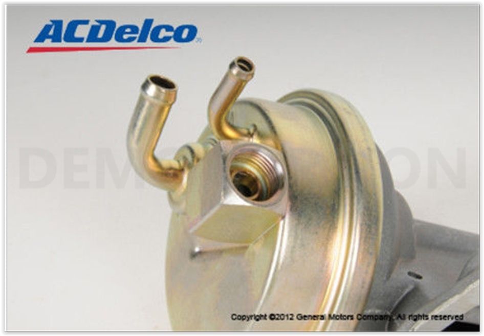
I have a weird issue with my 1980 Avanti.
My driveway is on a fairly steep incline. If I leave my '80 parked uphill on the driveway for any extended time, it refuses to start, cranks until the battery runs down but no gas is getting pumped to the carburetor (disconnected the line at the carb and nothing comes out while cranking).The gas tank is more than half-full.
If I get it down to the street where it sits level, and wait for awhile, it starts fine after cranking a bit, and runs strong thereafter.
I've checked and changed the inline filter.
I am thinking maybe a bad fuel pump or blocked feed line to the pump, but neither really explains why it starts and runs fine on level ground.
Any other ideas?
Anybody know the application for a fuel pump in a 1980 Avanti? I'd like to have parts in hand before tearing into it (actually, I intend to have it done and would like to be able to bring the parts along with me to the shop). Tried to take some pics with the car on the ground, but couldn't get any good shots of how the lines connect to the pump, the pump is really crammed between the front frame crossmember and the engine.
I thought perhaps Malibu, but the Malibu pump doesn't look right to me.
I did find a C10 pickup pump for a 305CI V8 that does have 3 tubes plus the hex fitting:
Wayne
-
Wow, gotta be careful on eBay!
If that's not false advertising, I don't know what is!
Guess he figures he's just reporting what the odometer says.
-
http://www.chevytalk.org/fusionbb/showtopic.php?tid/138939/
Happened to me once, leaked a quart or so after sitting for about a year on a level garage floor... filled it and drove it, hasn't leaked since. Beats me.

Anyone had an Avanti wrapped instead of painting?
in 1965-83 Avanti
Posted
Forum has been awfully quiet the past few weeks, so I thought I'd throw this topic out for discussion.
Anybody wrapped (or had a shop wrap) an Avanti? Pics?
Experience with wraps on other vehicles?
Is it practical? How long can a wrap job be reasonably expected to last and still look great, especially if it's not garaged, it's driven in winter, etc.
Does it require special attention when washing, or can you take it to the car wash like any normal car?
Seems like it would be a problem wrapping large panels devoid of seams, such as the roof and rear quarters that are all one seamless surface on the Avanti.
Also seems like it would be difficult to secure & conceal all the edges of a wrap.
Etc, etc.