


WayneC
-
Posts
537 -
Joined
-
Last visited
Content Type
Profiles
Forums
Events
Posts posted by WayneC
-
-
Since most of the stopping power is the front brakes, in my opinion its probably not worth the money and effort.
I recall seeing an Avanti with a rear conversion to disk at an Avanti car show, but that was long ago and I don't remember anything about it.
Turner had a conversion, but my understanding is that they have been out of business for some years now... http://www.studebaker-info.org/Tech/Bhend/turnerreardisk.pdf
Has been done on a '63; I don't know if 1983 has the same configuration rear axles/hubs. No kits currently available that I am aware of.
There may be info in AOAI magazine issue 134 (circa 2006) about the '63 conversion, which was also written up here (starts after the front brake conversion):
http://www.studebaker-info.org/Tech/sbca96/Cobradisk/cobradiskm.html
I believe the Avanti used a Dana 44 rear axle assembly, and Summit offers some conversion kits for them (dunno if they work on an Avanti):
Here is a Youtube video about a conversion on a Jeep Dana 44:
-
Now I can see your photos!
I tried bringing this thread up with 6 different browsers and could not see the photos (in your original post) in any of them. (Avast, Chrome, CyberFox, Edge, Firefox, Opera)
Nice looking Avanti!
-
Avanti83, maybe you could help me out... I don't know how to access the pictures you "posted". All I see is a big rectangle around a small circle symbol with a dash in it. Clicking that symbol does nothing.
One would hope for some forum instructions on accessing (and/or posting) pictures, but if there are any, I don't know how to get to them. When I POST pictures in a reply, the forum asks me to choose whether to upload the picture itself, or to allow the forum to just show a link to the picture; your post doesn't seem to have done either. I am suspecting your photos are hosted on a website that requires your personal (Avant83's) login.
-
After some thought, and considering that the gauge worked before you installed a new sender, I'm going to withdraw my prior post above.
I think the sending unit provides (variable) grounding and that perhaps you used a non-conductive (ie, not dielectric) sealant on the sending unit threads that prevents a ground connection. You could check this theory by using a test wire with alligator clips to connect the metal body of the sender to a grounded part on the engine to see if that gets the gauge working again. If it does, you'll need to remove the sending unit and thoroughly clean the threads in the block (wire bottle brush with some brake cleaner) and also clean the threads on the temp sending unit.
Or, other possibilities are that the new sending unit is a) bad or b) not compatible with the new temperature gauge.
To check to see if the sending unit is bad, you can probably use a multimeter to measure the ohms reading between the sending unit terminal and a solid ground to see if the reading changes as the engine warms. Here is a Youtube video showing how to check it: https://www.youtube.com/watch?v=puNKAW5Nurc
Perhaps the gauge is not compatible with the sending unit... you may need to contact the gauge manufacturer to see what sender they'd recommend for a Chevy V8.
For your further info, I did a search and found this on the net: http://www.secondchancegarage.com/public/653.cfm
-
deleted
-
This one is very similar, but 1/2" shorter in under-fender length than the MX-1:
Have you tried Nostalgic Motorcars? Have you asked a car radio installation business if they can get one for you?
**********
Finding a semi-automatic antenna would be the easiest solution, but it may be possible to do some relatively minor rewiring to use a fully-automatic antenna....
Automatic antennas get their 12v signal from the radio; not all radios have the capability to send that signal. A radio repair shop can probably add it to your radio... that requires radio removal, which isn't easy, but this is the best solution for the driver.
An automatic antenna requires 12v on one terminal on the antenna to raise it and 12v to a different terminal on the antenna to lower it, with a delay before shutting antenna motor power off after having raised or lowered the antenna. That function is provided by an antenna delay relay, either housed inside the antenna assembly or in a separate relay box (but likely internal to the antenna if it is an automatic antenna).
Your Avanti already has circuitry to raise and to lower the antenna and to turn the antenna power off after the antenna is raised or lowered... that function is being performed manually by the antenna toggle switch.
If your current antenna is the MX-1, then flick the switch up to raise the antenna, down to lower it.
There should be two 12v leads at your antenna, one to raise it and one to lower it. You can check those for 12v while someone operates the switch, to find out which wire is energized when the antenna switch is raised, and which wire is energized when the antenna switch is lowered (it is possible the "lower antenna" wire is always energized, but probably not). Once you know which wire in the trunk does which, then using a fully automatic antenna should be easy.
An "automatic" antenna has a terminal in its electrical harness connector to receive 12v from the radio, and another connector to receive 12v directly from the battery. Internally, there is a relay that is energized by the 12v "raise antenna" signal from the radio to raise the antenna and keep it raised; when the "raise antenna" 12v signal is removed, power is switched to the "lower antenna" output inside the antenna and when the antenna is fully lowered, it cuts off that battery power to the antenna motor.
You can use an automatic antenna if you provide direct 12v battery "lower antenna" power to the proper terminal on the antenna harness connector, and provide the "raise antenna" signal to the antenna with a toggle switch that applies 12v to the automatic antenna's radio power terminal. The power to the switch must come from a wire that is energized only when the ignition switch is in the "on" and "accessory" positions. Then just leave the "on" knob on the radio itself always turned on. Flick the toggle switch to "on" to power the radio and raise the antenna, "off" to turn the radio off and lower the antenna. If you forget and leave the toggle switch in the "on" position, then when you turn the ignition off, the antenna will lower anyway; when you start the car next time, the radio will turn on and the antenna will rise.
-
How about elaborating with some words that describe what the Dan Booth method is, as compared to what the SI approach is? I know a picture is supposed to be worth a thousand words, but some words of comparison/elaboration would be helpful to help those of us who haven't investigated to understand why the SI approach failed and why you expect this method to be better.
-
OK, thanks, sorry, obviously I got confused. I re-sent it to M&M
BTW, in looking at my profile, I am reaching the limit on attachments (photos, etc)... many are from posts that are quite old, doesn't appear to allow me to delete any, anyone know how I can get rid of some of these?
-
sent you a private message
-
Seems to me that either the left rear wheel wobbles when the car is driven (something wedged between the wheel and the axle end, or a bent wheel), or else the right wheel is also cocked at an angle (axle/differential unit is not square with the frame rails). If neither of those is true, and the wheel on the right seems properly-aligned with the body, then the body was damaged on the left side and incorrectly repaired.
Looking at your picture, it appears to me the wheel may be bent because the spinner/cap appears to be protruding straight out whereas the wheel looks misaligned with the spinner (cocked); if that's so, the wheel would be wobbling when the car moves. Have the wheel balanced, that should make a bent wheel immediately obvious to the tech doing the balance.
-
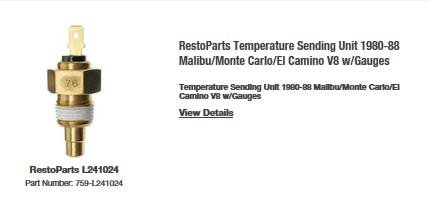
I don't have an '82, but I would expect the temperature sending unit to be on the driver side near the rear and look similar to this one...
-
Was the can just sitting loose on top of the radio?
There appears to be a clue written at one end, where the word "tune-" is visible in the picture, but partly blocked by the antenna cable... is there more there than just that word? I tried a search on the numbers that appear on the can, but had no luck with that.
Your car was built back when CB radios were in vogue, I think, so perhaps it's a part left over from a prior owners CB add-on device installation that made use of the car's radio speaker by outputting a particular radio frequency that the radio could tune to (perhaps the device itself only received CB signals, like a police scanner).
A part left over from a satellite radio aftermarket add-on product may be another possibility.
A build sheet for the car could possibly contain clues if this device was factory-installed.
-
As you've been told, you can purchase build information for your specific serial number car from Dan Booth at Avanti motors (they don't have a website)
https://www.superpages.com/bp/wixom-mi/nostalgic-motor-cars-L0010939693.htm
-
Jim, that is the Avanti II electrical info I referred to in my post. Thanks for that find... I bought the booklet some years back, but lost track of it.
-
The only books available are for the original Avanti, but most of that applies to your '81 as well. There was an electrical addendum, of sorts, offered by a private seller some years back, dunno if that is still available; It covered some circuits that were added in the later Avanti II years (hand-drawn diagram sketches).
The books below are indispensable, and they can be found on eBay as well as from some of the Avanti parts suppliers:
Avanti Workshop Manual (white cover)
Studebaker Avanti Chassis and Body Parts Catalog (black cover)
Here is an excerpt from the parts catalog:
-
Here is an illustration from the parts book.
-
While I agree it is good practice to inspect and lube the pump pushrod when installing a fuel pump, the Chevy small block V8 has been produced in the many, many millions and fuel pump pushrod failures have not been an issue so far as I know. The pump is driven by a lobe of the camshaft, which is throwing oil in all directions inside a crankcase full of oil mist. Prolonged periods of not driving the car would probably be a more common reason for failure. Or an internal coolant water leak, or a very, very high mileage engine, or use of vice grips on the pushrod when installing a fuel pump. Also, there is a bolt on the front of the engine that aligns with the pushrod and some folks use a long bolt in that bolt hole snugged against the pushrod to hold it in place while they install a fuel pump, then replace the original bolt; I've always used a dab of heavy grease on the rod to hold it in place while installing the pump.
Not an issue that would keep me up nights.
-
If you didn't have the speakers connected to the new radio, why would you expect to hear anything when you hooked up your phone to play music?
Is the new radio (and the old radio, for that matter) a single unit or does it have a separate amplifier unit?
Does the new radio have provisions for 2 wires to each speaker (8 speaker wires)? Did your old radio also have provisions for 2 wires to each speaker? Sure, bypassing the old wires by running new wires is OK, but certainly more difficult than just using the old speaker wires. Do the new speaker wires appear to be a significantly heavier gauge than the old ones (meant perhaps to carry more amperage)? If you are tearing the interior out as part of your restomod, then running new speaker wires would not be as difficult.
Hard to visualize your old wiring from your description, but the four existing speakers must connect into the back of your current radio, and by disconnecting the plug from your old radio and using a multimeter to test continuity from the old harness plug to the end of each speaker wire (wires disconnected from the speakers), it should be easy to determine which wire goes to which speaker; in fact, my guess is that you may get speaker buzz if you leave the speaker wires connected and use a multimeter to test the continuity of speaker wires from the radio plug end only, thus making it obvious which speaker is connected to the wire pair being tested.
Pictures of the existing plug(s) and the back of the radio would be helpful... Hard to understand your description ("they all have red and white wires"???... is that two separate colored wires, one red and one white, or are they white wires with a red stripe? Where do the "brown wires coming out" go to (I assume they must plug into your old radio somehow). "green wire has a red wire that connects to my radio"... what does THAT mean ?????
-
How about some background...
Why are you wanting to change out the Blaupunkt?
If your Blaupunkt doesn't work, have you considered having it repaired? Blaupunkts are considered excellent radios.
Did you test the wires (in the harness that connects to the radio) to see which supply 12v to the radio (switched and unswitched, respectiively) as suggested by Avanti83?
Does your car have multiple speakers? Where are they? Did you look to see what color wires are connected at the speaker(s)?
Is your antenna controlled by the radio, or by a manual switch?
BTW, the ground wire that connected to the Blaupunkt could just be connected to the mounting screw/bolt that will support the rear of the radio case (the replacement radio probably assumes you are installing in a car with a metal dash, in which case the mounting screw(s) and knob posts would ground the radio case to the car)
If you are not comfortable with simple testing of wires with a multimeter for 12v or for ground continuity, and you don't have a friend that can show you how, or you don't feel comfortable with online tutorials on how to do it, then by all means let a pro do the job. There are numerous tutorials on Youtube:
-
That's a strange/vague question. Are you looking for the power/antenna/speaker connections of a suitable replacement radio? Any replacement radio will likely have different connections than your current radio.
....EDIT 10/11/2018: I think I see now that I interpreted your question wrong, you are looking for wiring info for the stock 1983 radio.
Since you already have a post asking how to remove the radio, I assume your radio has issues? Perhaps it could be repaired. Or is there some other reason you wish to replace it?
My advice: First find a radio that fits into the dash (that's the tough part, particularly the space available for the radio face/knobs), then you may be able to find info on the internet about the connectors on the back of that model radio, and then find suitable male/female connectors that will accommodate the wires needed to make those connections for the chassis plug(s) from your old radio to the new radio. You might want to consider splicing into the old chassis harness without cutting the harness connectors off, or better yet, find connectors that will plug to the old chassis harness connectors, even if it is wire-by-wire, so that you can make your own adapter harness to mate the old chassis harness connector(s) to the new radio, and thus be able to convert back at some future time if need be. I did that when I replaced the radio in my Jaguar XJS a few years back.
An alternative is to mount a modern radio in the glove compartment or the trunk, and resolve the harness issues for those locations. I suspect there may also be vendors offering radio systems where the controls are in a hand-held device and the radio itself is hidden somewhere in the car.
I used a Blaupunkt Frankfurt in my '71, but that was many years ago and there were numerous iterations/models of the old Frankfurt, commonly used in Mercedes & Porsche (and perhaps BMW and VW as well) back in the sixties and seventies; further complication is that Blaupunkt made European and US versions. Since they are original to those European collector cars, they are quite pricey these days, especially in good working order. I also own an '80 Avanti, and it also, I think, uses a Blaupunkt radio that was likely original to the car. I don't have an '83 Avanti, so I am not familiar with what radio was used that year.
Here is an eBay search link for Blaupunkt Frankfurt radios https://is.gd/qOqos3 ...note that there are variations and that nice working examples are expensive
Here are several sellers offering older-style radio configurations, but with modern improvements (I haven't used their products so I cannot vouch for their quality); you can likely find more such sellers on the 'net, and if you search those sites, they probably show info about the connectors on their radios...
https://www.classiccarstereos.com/studebaker-radios.html
https://www.streetrodhq.com/dept/Radio.html
-
I don't have an answer, , but I'm sure it IS mounted on a bracket ...replaced my radio many years ago with a Blaupunkt so I know removal can be done (with a lot of frustrating wriggling and repositioning, and maybe even a slight amount of fiberglass removal to provide a slight increase in the size of the dash hole in selective locations... maybe the corners, can't recall exactly, and I think it can be removed from the passenger side console although some A/C hoses may need to be detached).
Here are several hits I found with a Google search:
https://www.studebakerparts.com/studebakerparts/store/s/html/pages/avantiam-fm.html
Please, you would be doing others a great favor if you document the removal with words and pictures as you go along, and post the method you find successful.
-
Most likely reason is a vacuum leak in the power brake booster unit. I had that problem (front brakes dragging) back in the 1980's with my '71 Avanti but I can't remember how I determined it was the booster.
One possible way to test is to find the vacuum hose from the intake manifold to the booster unit, disconnect it at the manifold and use a hand vacuum pump (with gauge) to apply vacuum to the booster vacuum hose and see if it holds the vacuum.
I sent the booster to "Booster Dewey" ... http://www.boosterdeweyexchange.com/dev/
-
It was a long time ago, designed for my Jaguar XJS, and may or may not be applicable in principle to an Avanti... but I'll try to address several of the questions posed:
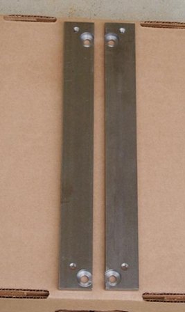
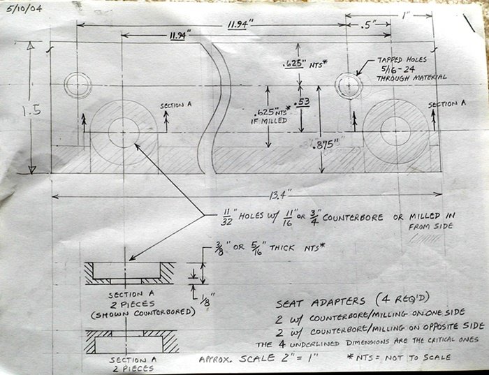
The material left on the adapter after counter-boring is 0.125", which is thicker than the material that retains the captured nut (in the floor) that the adapter bracket bolts to. In other words, the weak point is not my bracket/adapter, but the vehicle's original mounting points for the seat, so should not compromise safety.
My first job out of high school was as a draftsman, and I later spent time on the drawing board with Chevrolet during and after college... I realize not everyone understands drafting notation. My drawing was a representative sketch, not a real mechanical drawing. The orientation of the sketch/drawing is looking down on (top) of an adapter, with the middle of the adapter shortened (cut away) to fit it on the sheet of paper. Compare the drawing to the photo of the left & right brackets... the difference between left and right brackets is that the counter-bored holes are on opposite sides of the bracket.
The counter-bore is to recess the heads of the adapter-to-floor hold-down bolts so they don't interfere with the seat slider that bolts atop/onto a pair of adapters (left and right). Left and right brackets bolt to the floor, then the seat/slider is bolted to the brackets. Offsetting the bracket hold-down holes from the seat fastening threaded holes (towards the front of the bracket) would provide more space for the drivers legs, at the expense of rear passenger leg room, of course, but offsetting in the opposite direction could bring a shorter driver closer; I wasn't trying to change the driver position, so mine were only offset by 0.5", by necessity because if much closer the bracket hold-down and seat hold-down holes would interfere with each other.
There are many ways the adapters could have been lightened and streamlined, this was my version of quick, simple, and cheap
-
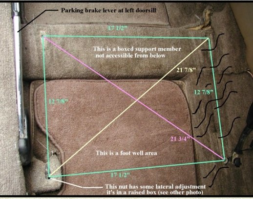
I owned an '84 XJS; when the leather seats got badly worn, I purchased a set that were in very nice condition from an XJS a few years newer than mine, thinking they were a direct fit, but to my dismay, they were not. So, I set about designing a set of simplistic adapters; the adapters would bolt to the old nuts in the floor (bolt heads recessed below the adapter surface) and the newer seats would bolt into the top surface of the adapter such that the seat slider would still work, the only caveat being that the seat would sit slightly higher (the thickness of the adapter, which needed to be about 1/8" thicker than the head height of the floor-mounting bolts). The adapters were rudimentary, simply 2 strips of 3/8" x 1-1/2" steel per seat (overkill, really), with countersunk holes to bolt the adapters to the floor and threaded holes for fastening the new seat's slider bolts; I had a metal shop do the machining for me, and I was overly-obsessed with keeping costs minimal, so simplicity was key,.
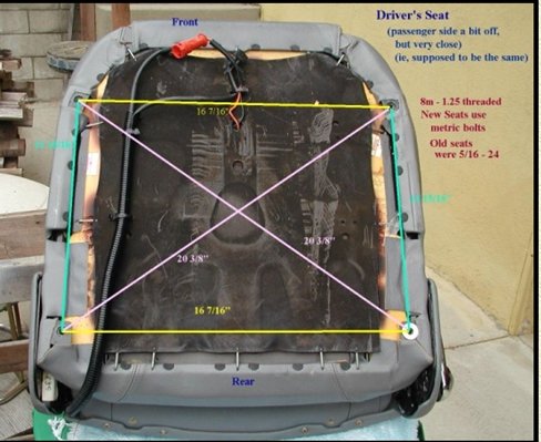
If I were doing it now, I'd use aircraft aluminum welded into an "H" design rather than a box, with possibly 2 cross-bars placed forward so as to allow accessible passenger foot space below the rear of the seat; I didn't know where to find aluminum stock back then before computer searches became so easy. These photos should give you an idea of how I determined the dimensions of the adapters:
Gas cap Avanti biz
in 1965-83 Avanti
Posted · Edited by WayneC
Don't have a later Avanti, but my guess is it has something to do with unleaded gas and emissions, that the fuel tanks made for unleaded fuel have a different (smaller) filler tube specifically to prevent use of the old vented caps and pump fueling nozzles. Dunno when Avanti made that change. IIRC, when unleaded gas became law in the mid-70's even the fuel pump handle & nozzle assemblies were changed out (for a smaller diameter filler nozzle) so that leaded gas could not be pumped into an unleaded-gas vehicle by mistake during the transition (the old larger-diameter nozzles would not fit into the new filler tubes). If you could put an unvented cap on a vented-cap vehicle, vacuum would build in the tank and lines (and carburetor) as the fuel is used-up, which in turn would fight the suction of fuel pumps (as opposed to in-tank electric fuel pumps in cars which then need a fuel return line... those unleaded-gas tanks vent via other methods).