


Zedman
-
Posts
172 -
Joined
-
Last visited
Content Type
Profiles
Forums
Events
Posts posted by Zedman
-
-
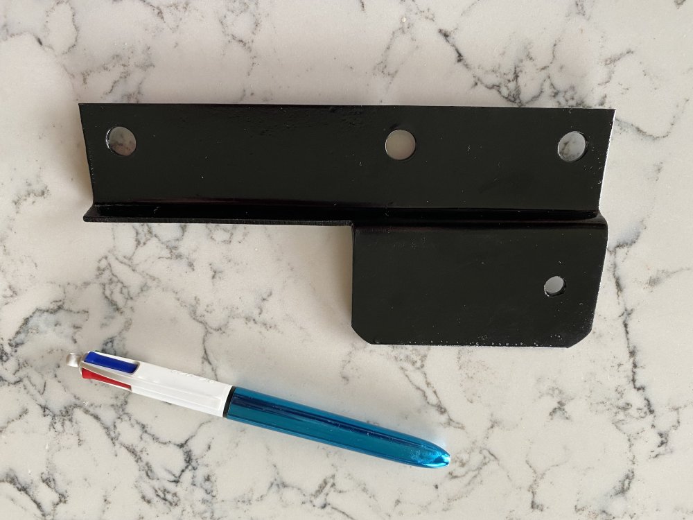
I have finally figured out what it is !... Brad Bez's reply sent me looking at my photo records again. The bracket is on the other side of the Frame to the Battery. The upturned edge was the kicker. It is the support for the base of the Charcoal Canister. Only goes to show. you can't take enough photos on big jobs.
The part is bagged, identified and catalogued for reassembly. Thanks for looking, all.

-
4 hours ago, brad said:
Maybe under battery reinforcement?
Thanks Brad, but not there either. I have a clear photo of the Battery Reinforcing bar. It was rather rusty, having had some exposure to salt spray. I found it already unbolted and left lying with the motor and transmission out of the body. Beats me 'cause I've been pretty vigilant on this job 😕
-
On 6/1/2023 at 3:38 AM, 1inxs said:
I wonder if that is the trunk popper motor bracket?
No. I have not removed that.
-
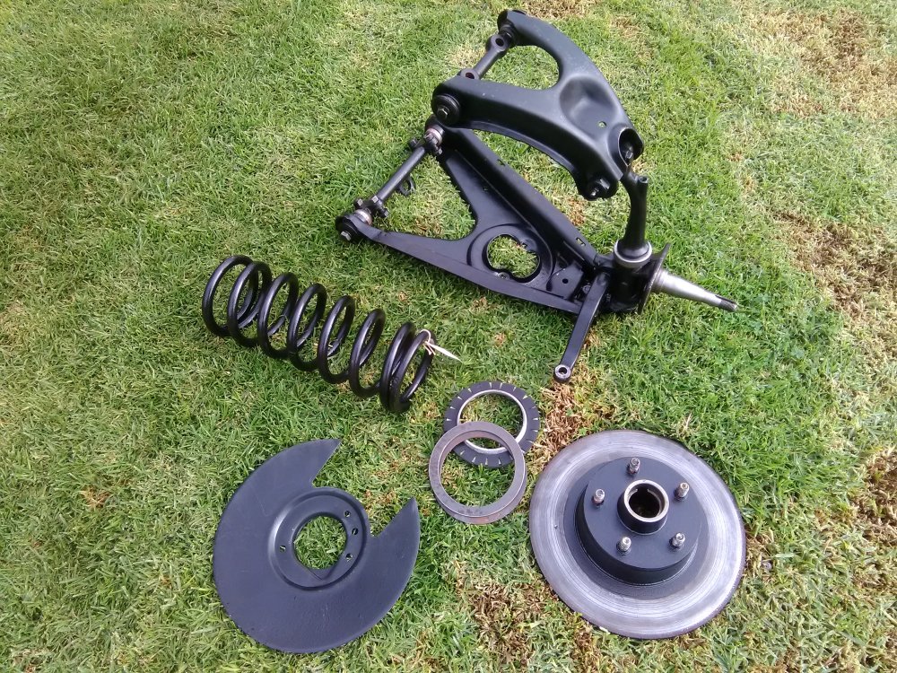
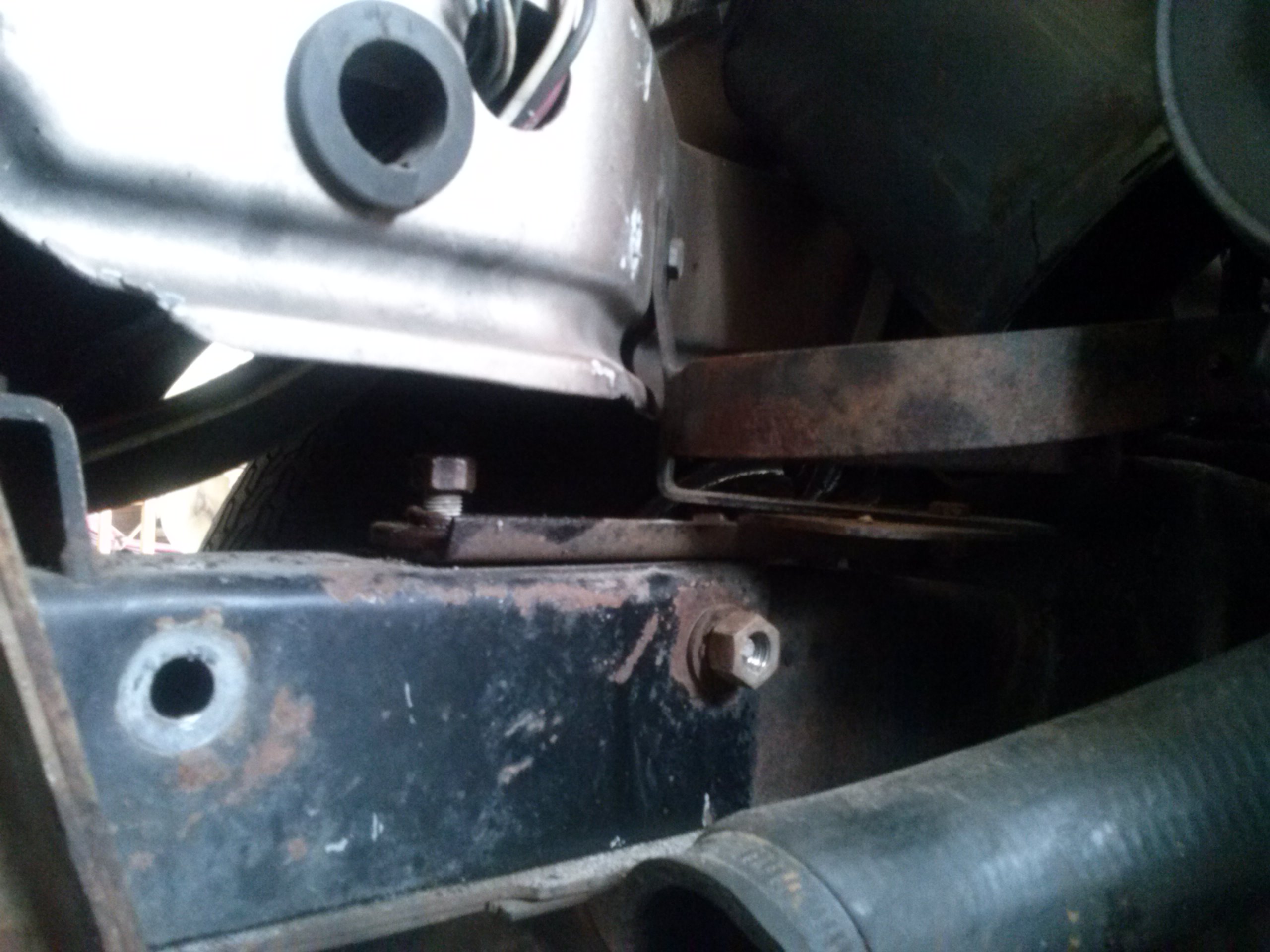
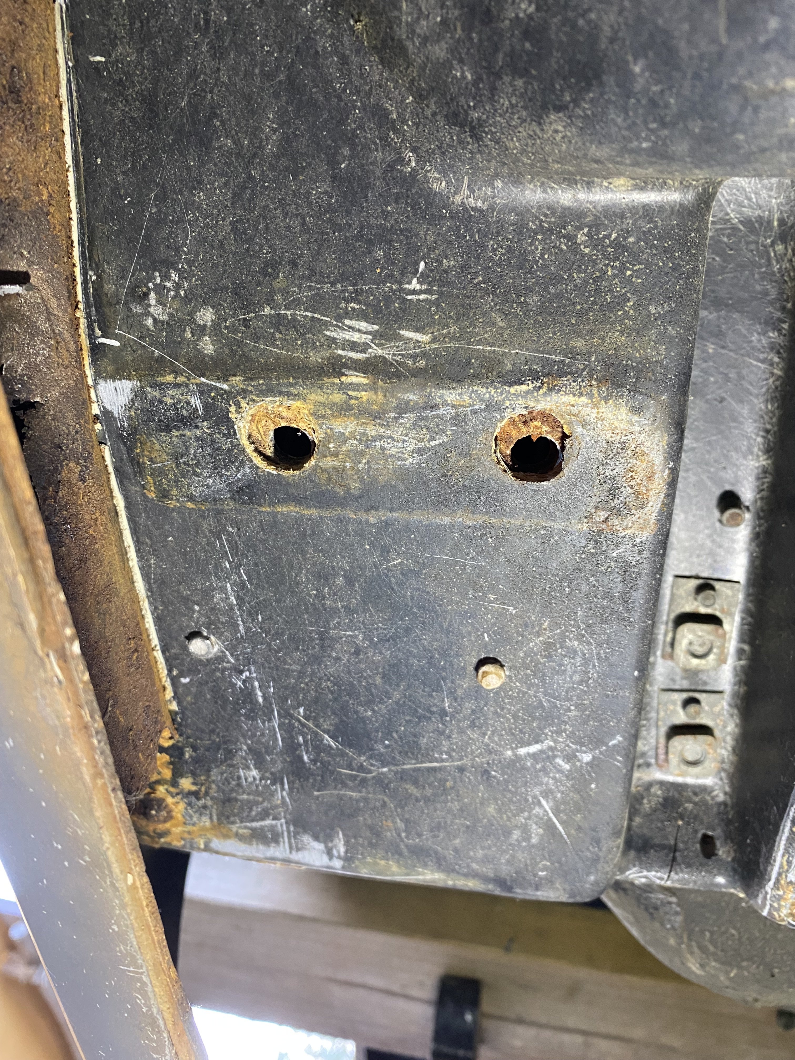
Hi All- Despite vigilantly photographing everything I do to during my 1981 Avanti's strip- down, the location and purpose of this Bracket eludes me completely. I don't remember removing it and despite checking my photos I can't see it anywhere. I believe that it is something off the engine/transmission. Can somebody let me know where it goes (politely ! 😁)? In the army they used to say "If it moves, salute it, if it does't- paint it.... so I did.
-
I have removed some of the bumps and lumps of fibreglass and rivets from the bottom lip of the right hand side rocker panel. This was done to effect a better fit for the CI 'Outer Rail'. This was a rotten, filthy job but was achieved with an inexpensive belt file, purchased to do the job I noted with some disappointment that when the rail was fitted in place the end sections with 'joggled ' shapes to fit the floor fitted perfectly but the whole center length will need about 3/16" of packing to fill the gap running along there. This section is going to be riveted. I am thinking of obtaining a strip of PVC to pack the gap. The 'Tab' at the forward end that gets two rivets from the wheel arch, is a poor fit and will need massaging into the correct angle with a hammer and dolly. Weather is getting decidedly colder, so I will need to brave the elements if I am to get this job done. We don't (generally) get snow down here, thankfully !

-
I'll ask this question while the topic is still up.... I know the shims are supposed to go on the right hand side of the Rear Axle, but if they are placed on the Left side, does it make any difference apart from knowing which side to look?
-
On 5/19/2023 at 4:36 AM, 64studeavanti said:
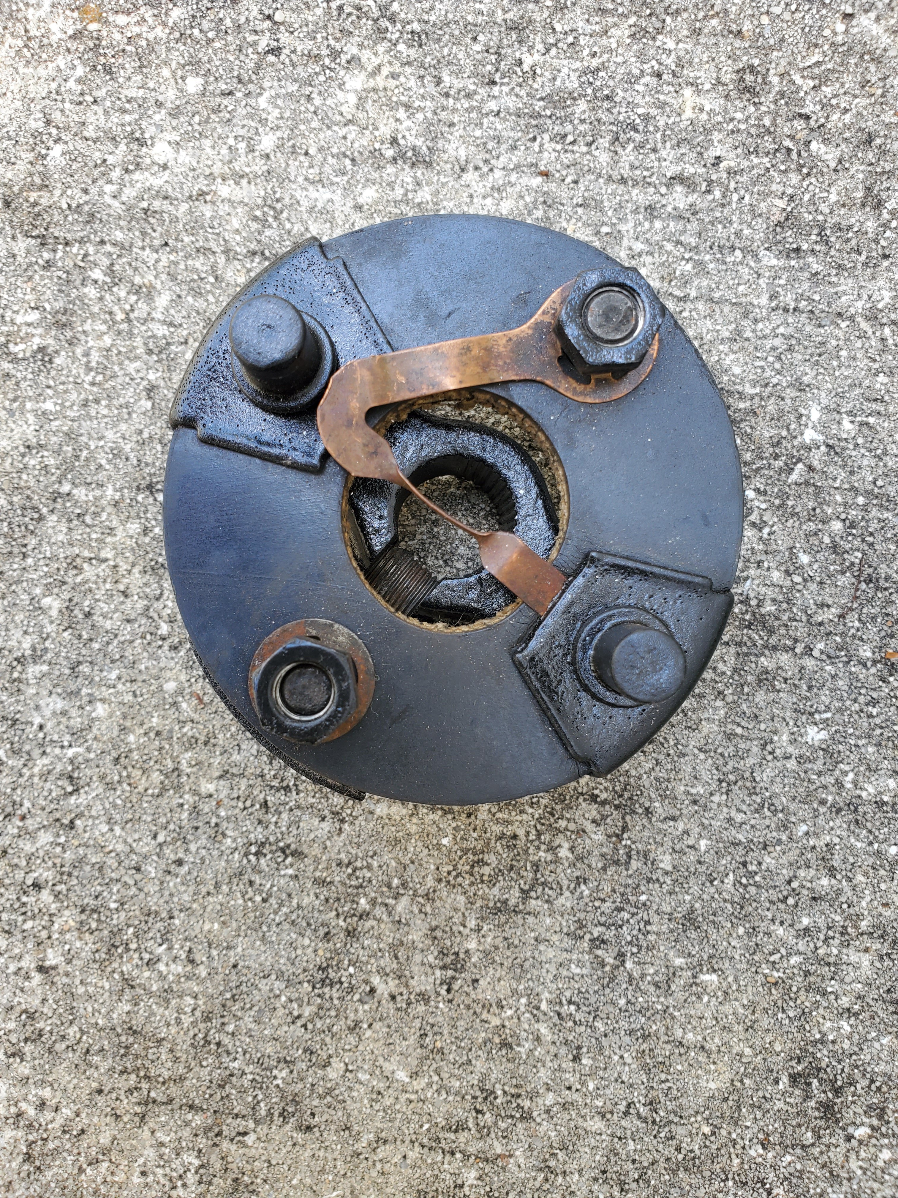
FWIW, picture of correct rag joint with horn jumper.
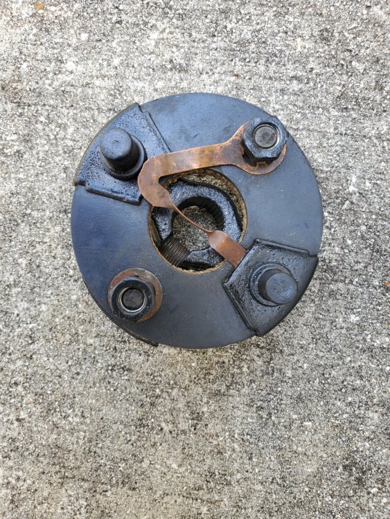
Aha ! looks like I only have a half of one !... Thanks for this photo. Good article here https://www.nostalgicmotorcars.net/uploads/1/2/4/8/124888690/ragjoint_issue191.pdf
-
The annular 1/8" Spacers are listed with Studebaker International as 526830 Front coil lining spacer 1/8" thick. I am having my doubts about what I quoted about the positioning of these- they may well have gone on top of the Ally Spacer (I was positive I had a photo...) 🙄
-
Having pulled out the front suspension, I found the Aluminium Spacer AND a stack of two 1/8" annular discs under each of the Springs. The Steel discs were found at the very bottom of the Control arm spring seat and were quite rusty. The Ally Spacer went on top of these. Under the Spring, I found no rubber insulator like the one positioned at the top but I'm going to trial one glued to the Aluminium Spacer to see if it's quieter
 .
.
-
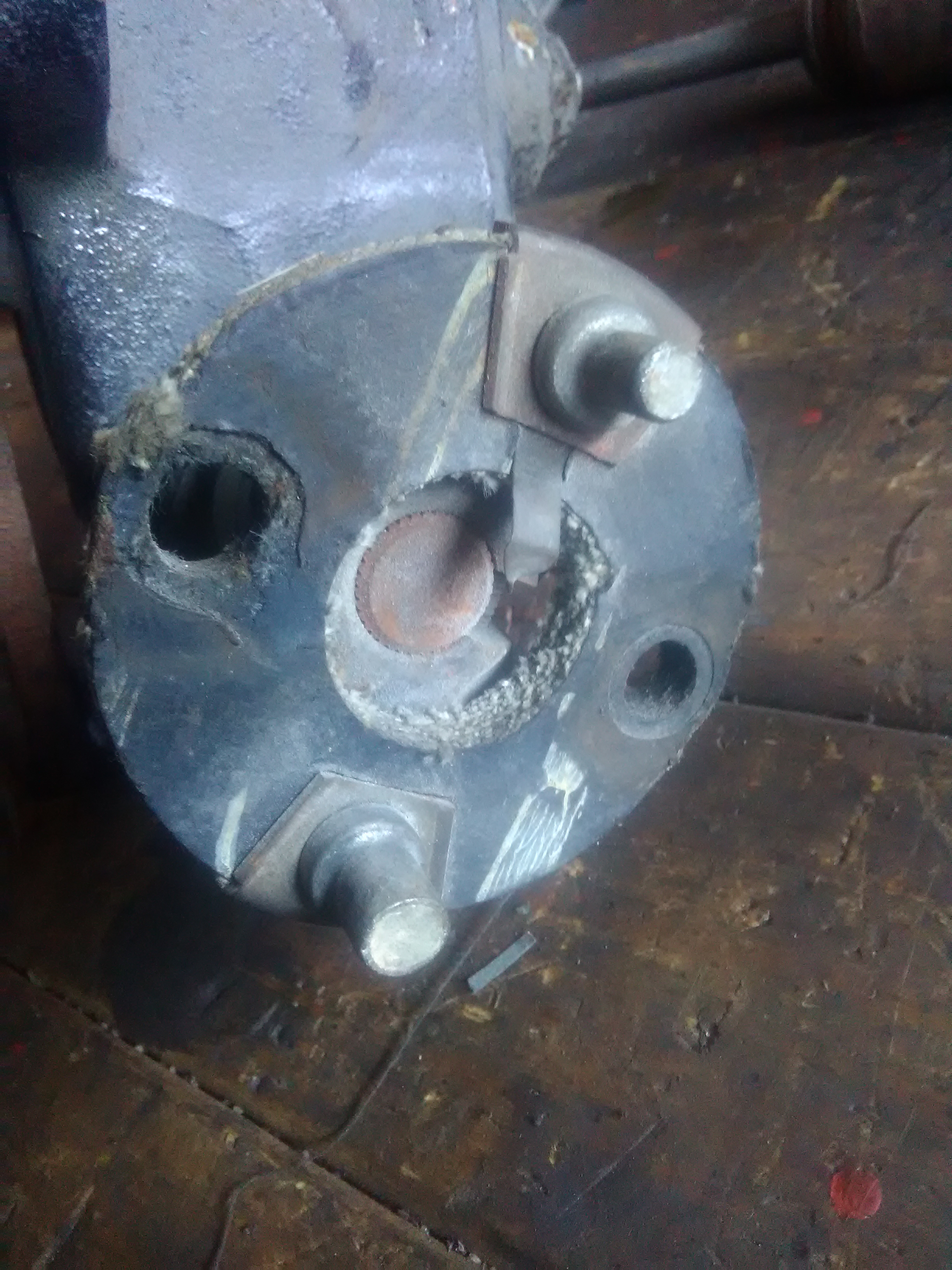
Hi Bill- While you're looking around, check the Steering 'Rag Joint'. There is a little brass contact in there- at the centre. Its function is to relay an earth either side of the rubber. Mine, shown here, I don't believe is as ought to be- bent up. Some people lose this little feller a or prefer not to bother with it, so they employ a 'jumper wire' to connect both flanges of the steering coupling.

-
Send 'em back- The holes are way oversized. 😬
-
The Transmission seals kit should be readily available from many vendors as it has a shared lineage. As I was told by a late learned rebuilder, "Ask for a Kit for a Warner Type 8 Small Iron Case and it will be covered".
A USA specialist is https://www.fatsco.net
eBay example https://www.ebay.com.au/itm/281044057801
Note that many kits do not have bearing bushes or even clutch discs included and you may require to source these specifically. The imperative advice I also received was to always replace the bushing at the Front Pump nose (where the input shaft runs). Many of your other bushes will be ok, but you ought to measure 'em and consider their fate. I would suggest you seeing this this Blog http://studebakerflightomatic.blogspot.com/
These transmissions are quite easily overhauled and the Studebaker Shop manual is very good.
-
If your fluid level is correct (checked whilst the car is actually in gear and running- careful) then I would suspect the rubber O rings in the Drums may have failed; they get flattened out and brittle with age.. Just how old is this transmission?
-
Hi Bill- Do you have original Bendix Brakes on the front? I'm betting Myers' will need to remove the Proportioning valve as It will be redundant in an all disc system. Looking forward to your posts 👍
-
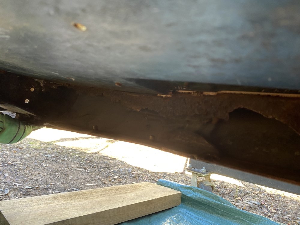
This message is intended mainly as a bit of a "show and tell" for anybody interested in Torque Box replacement. There appears to some detail alluding to minor issues missing from the various blogs I've read and I have picked up on some of these. If anybody has any comments or advice, do add it- I'd prefer not to boob this job.
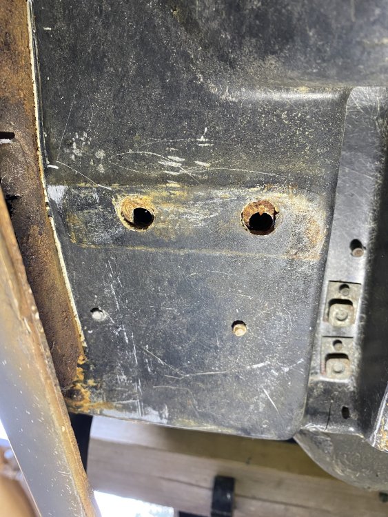
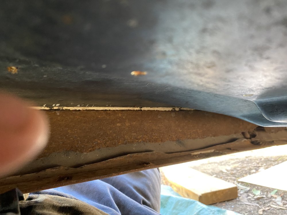
I have removed the rusty vestiges of my '81 Avanti's RH Torque box in preparation of fitting Classic Enterprise's two-peice replacement. In trial fitting the kits' 'Outer Rail' to the inside of the Rocker Panel, a good fit was impeded by various pop rivet ends (both under floor and along the sill) and the thickness of a white plastic/fibreglass strip running all along the lower lip. I removed offending rivet ends by grinding or filing and tried the new Rail but it was still an unreasonably tight fit. For this reason, I have started to remove the strip and various lumps of Fibreglass along the Rocker inner. I assume that the 2mm thick white plastic strip is actually the "Filler Strip" mentioned in Classic Enterprises' fitting instructions, and in my case I reckon it oughta go. I noted a significant gap above the middle section of the Rail and the floor underside which I feel should be filled before riveting, with a long shim of some sort. The way things appear and because I have the body completely devoid its Frame, I'm surmising that the boxes might be able to be fitted in one piece (assembled and welded) and with no rivets required through the Rocker Panels. The CE kit requires no cutting and repair of existing fibreglass. I have also drilled out the Rollover Bar Bulkhead studs- these are to be redrilled and tapped for 1/2" UNC setscrews supplied in the kit.
.thumb.JPG.dc6fdc4fdeac848694f6f8cedbd499d0.JPG)

-
13 hours ago, 1inxs said:
Zedman, Sorry, yeah, after your post, I decided to put more effort into researching my parts manual for the answer. For Avanti with power steering I see a listing for the listing for 7/16” -20 x 2-1/4” and a washer 7/16” - 20, but I don’t see a nut for a power steering car. I also didn’t think there was a nut involved in this assembly. Have I made a wrong assumption?
Thanks
Robert
Geeze, Robert- my bad... No nut required, at all. The length is also 2 1/4", which is just long enough. I was thinking of my 1961 Hawk non PS RHD Bellcrank- uses a nut. Just ensure that you have enough threads on the length to not get thread-bound when tightening, otherwise employ a flat washer or two.
-
I checked the head markings and it's a class 8 UNF. The parts book states it is 7/16"-20tpi x 2 3/4" long. Don't settle for a class 5.
It should be available in any big fastener supplier. Order a high tensile nut and a star washer to go with it .
If you're a stickler for originality, as I am, SI will supply you a new one with the nice 'TR' marking on the head. 😉
Grease it for torquing.
-
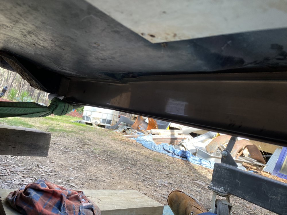
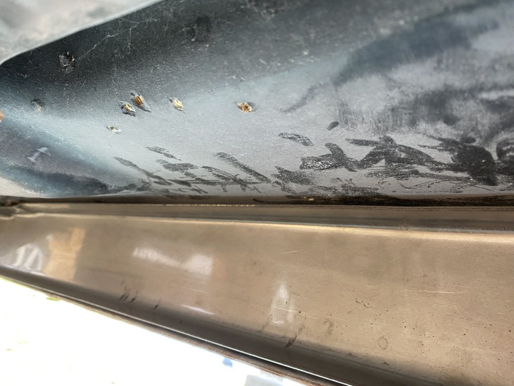
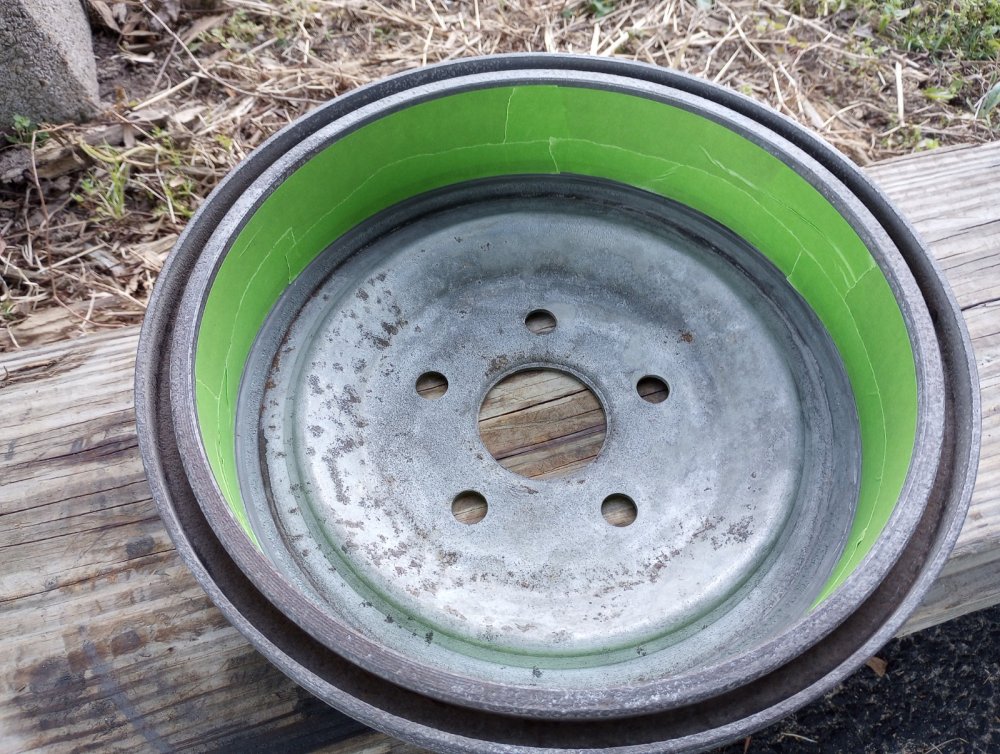
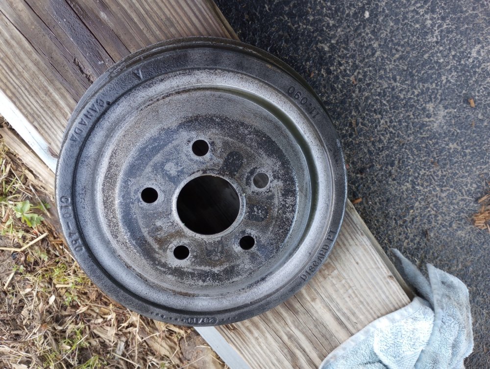
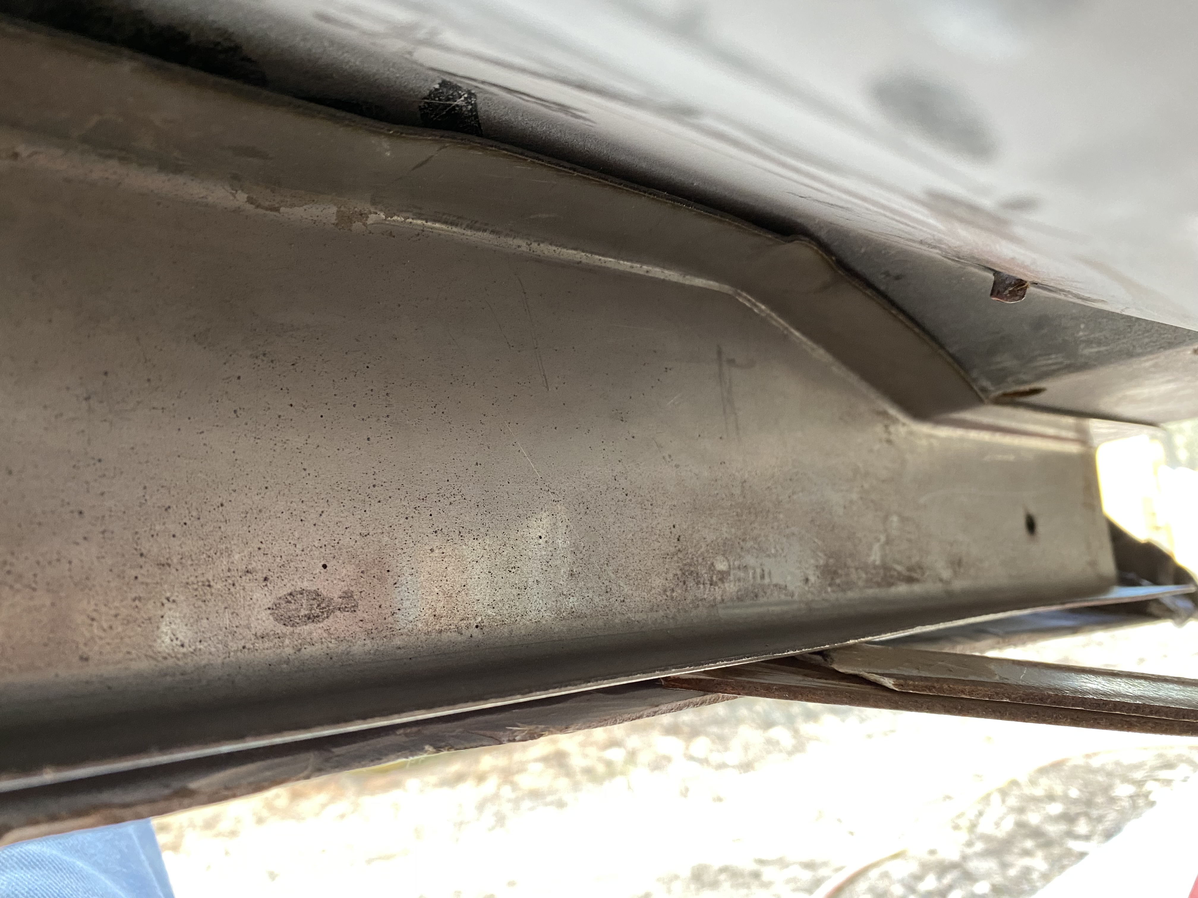
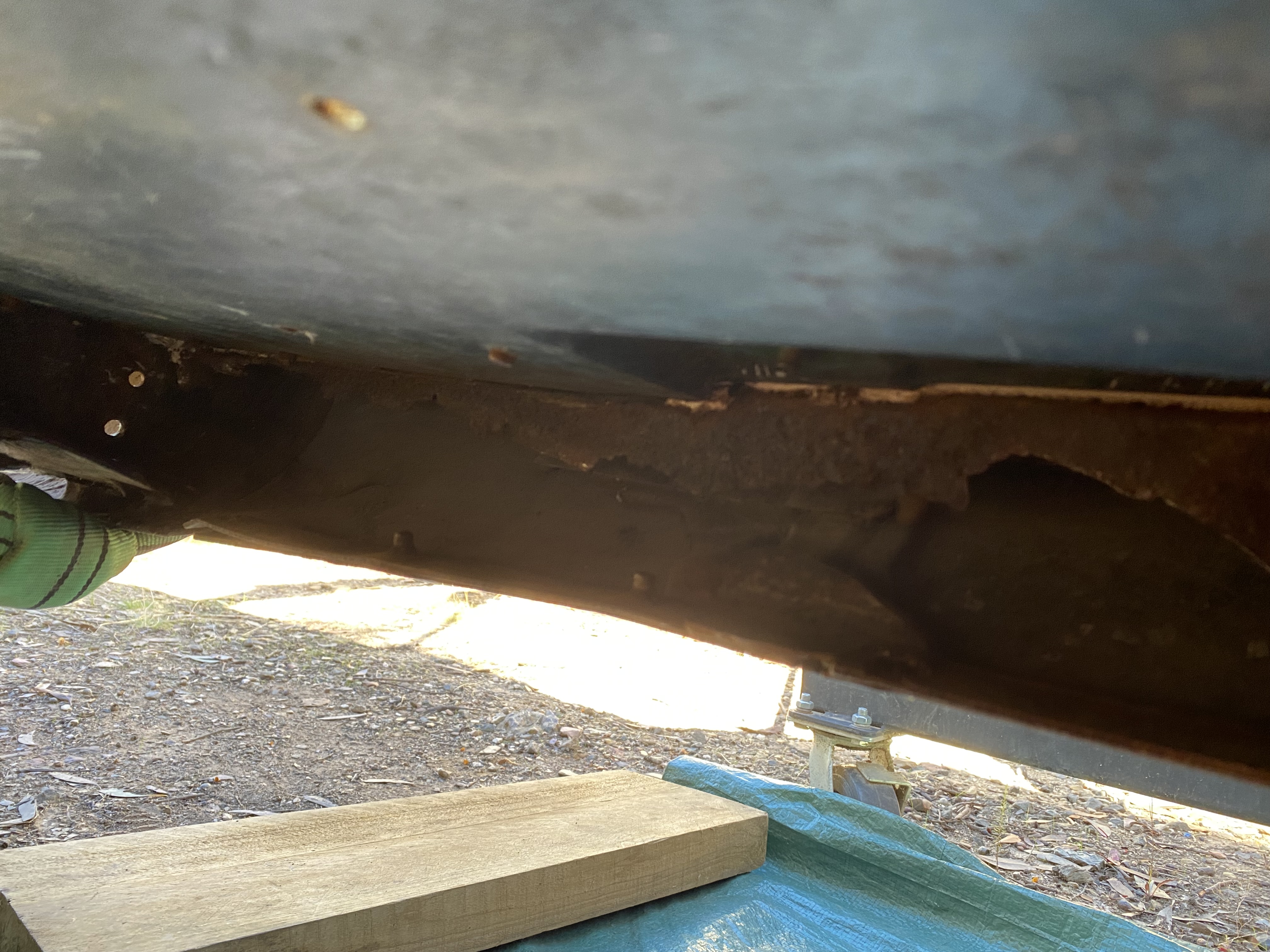
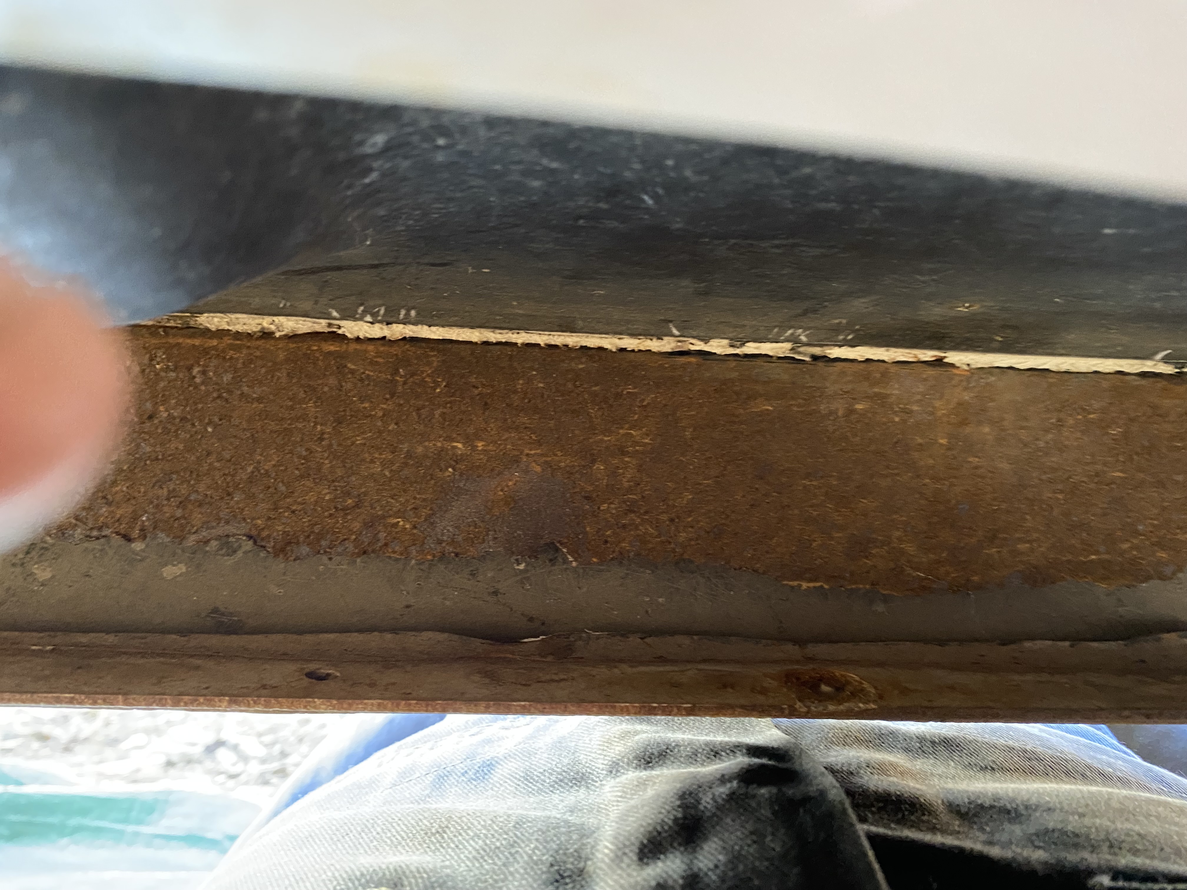
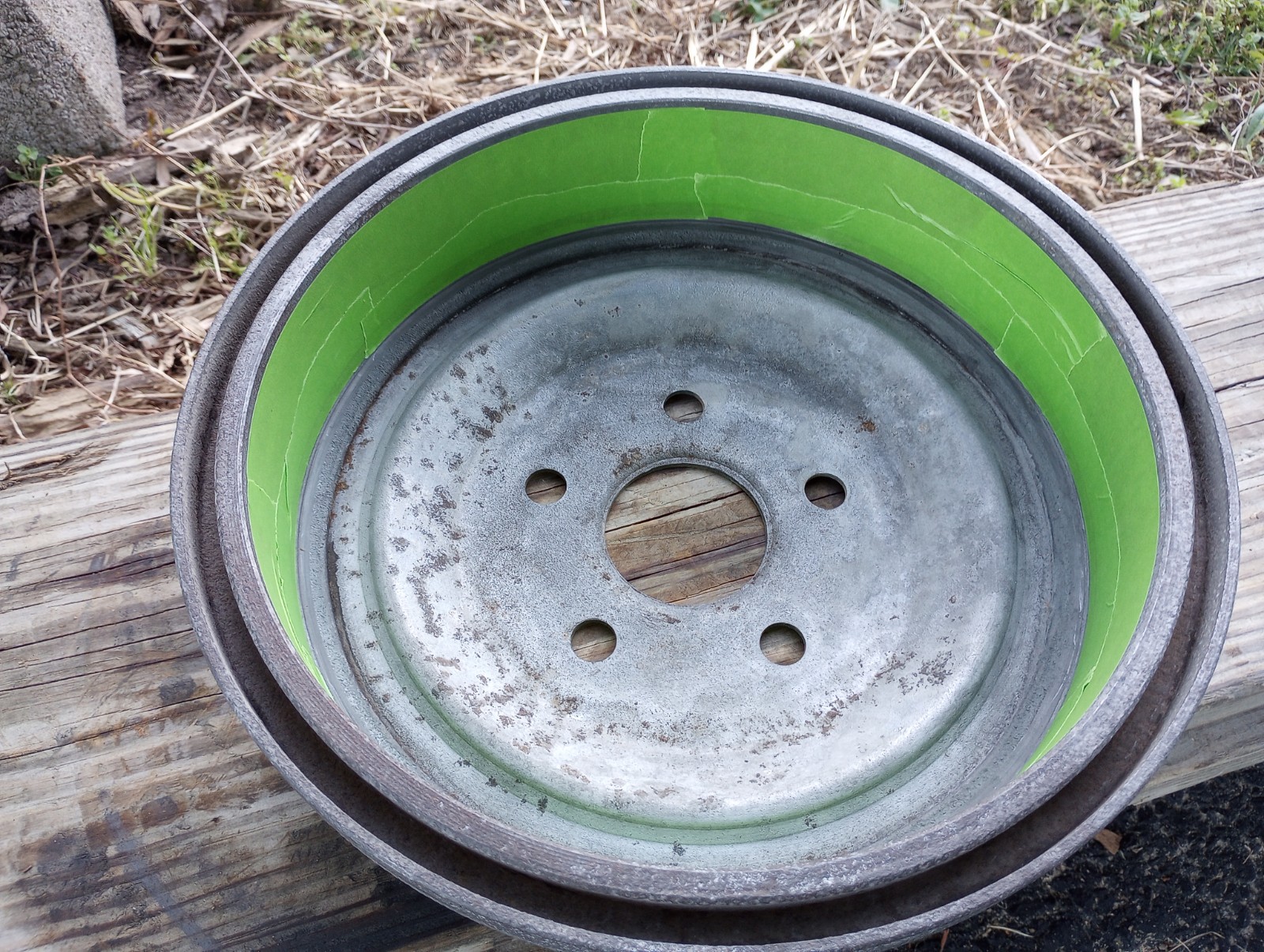
Studebaker Chassis rails have a plate welded to the bottom of the 'hat section' from front to rear. In that regard they are indeed 'boxed' and this is the norm. The rear Brake Drums are in fact 11" dia and this is also standard for these Avantis. I noticed the crappy welds (in Australia this is known as "cocky cack" 😁)executed at the area where the Engine mounts bolt up. It appears that somebody just welded the packing shims in place and it probably doesn't mean it's cracked there.... but I wonder what's underneath? 🤔
-
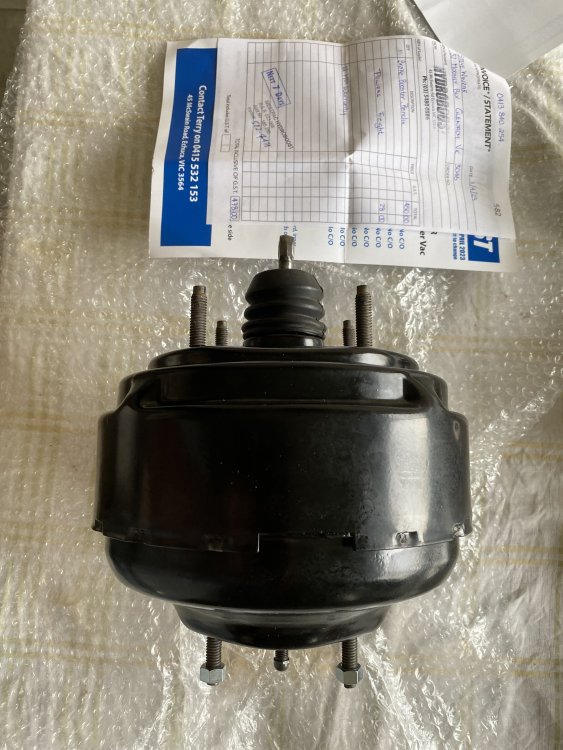
I'm personally glad you posted this outcome ! I looked at all my photos for my own Brake booster and Master cylinder where they interface and I recalled there was no evidence of a seal in there. Seeing the vacuum is on the front half of the booster drum, it makes sense to have a gasket there....🙄. I will follow your lead when I put my system back together- Thanks. 👍
-
If your Booster is the same as mine and I suspect it might, yank it off and see if you can get it rebuilt- just had mine done. Bendix unit same as early 70's jaguar XJ6, some Caddies , Volvos and AMC's
-
11 hours ago, SCPO-PD said:
That is the current game plan. I just received my set of QuickJack 7000 car lifts to get RQB 3616 up off the ground (2+ ft) so that I can better degrease, pressure wash, phosphate treat, & painting the frame.
I have looked at the brake lines and actually ordered a set of replacements but they were for the 63/64 Studebakers and not 65-83 models..... I returned them and got the shocks and a few other items. All of the current lines (minus the rear lines along the axle seem to look pretty good. I have flushed them all out w/ brake cleaner as noted above (I think). I do need to replace the line feeding the rear driver side drum as I twisted it off while trying to disconnect at the cylinder. Going to hit the parts store on the way home to see what I can find. Fingers crossed......
Grab a set of line wrenches if you don't already have 'em- these are dead set invaluable. So I take it you have decided to not remove the Frame, which is a fair call. You are up for a heap of dirty work under there, but the reward will be enormous. I was given some 'Action Gel' to try, on the proviso I reported back to the supplier on its efficacy. This stuff clings, works exceptionally well and I can recommend it. However the fellow on this link has a great idea to thicken Phosphoric acid if you already have a lot of Evaporust....
PS on the QuickJacks - I hope you have seen some of the many videos warning of 'false locking' of these units. Please do employ a good set of Jackstands or block it up.
-
Well done on your efforts so far- I for one appreciate the photos. I note the surface rust on the Frame and everything else. I have replaced all my steel Fuel Lines as well because of salt corrosion. One line actually broke in half because it was so badly corroded. You might want to check 'em while you're at it.👌. After you attend the meet are you considering lifting the body to clean up the Chassis?
-
On 4/14/2023 at 6:56 AM, SCPO-PD said:
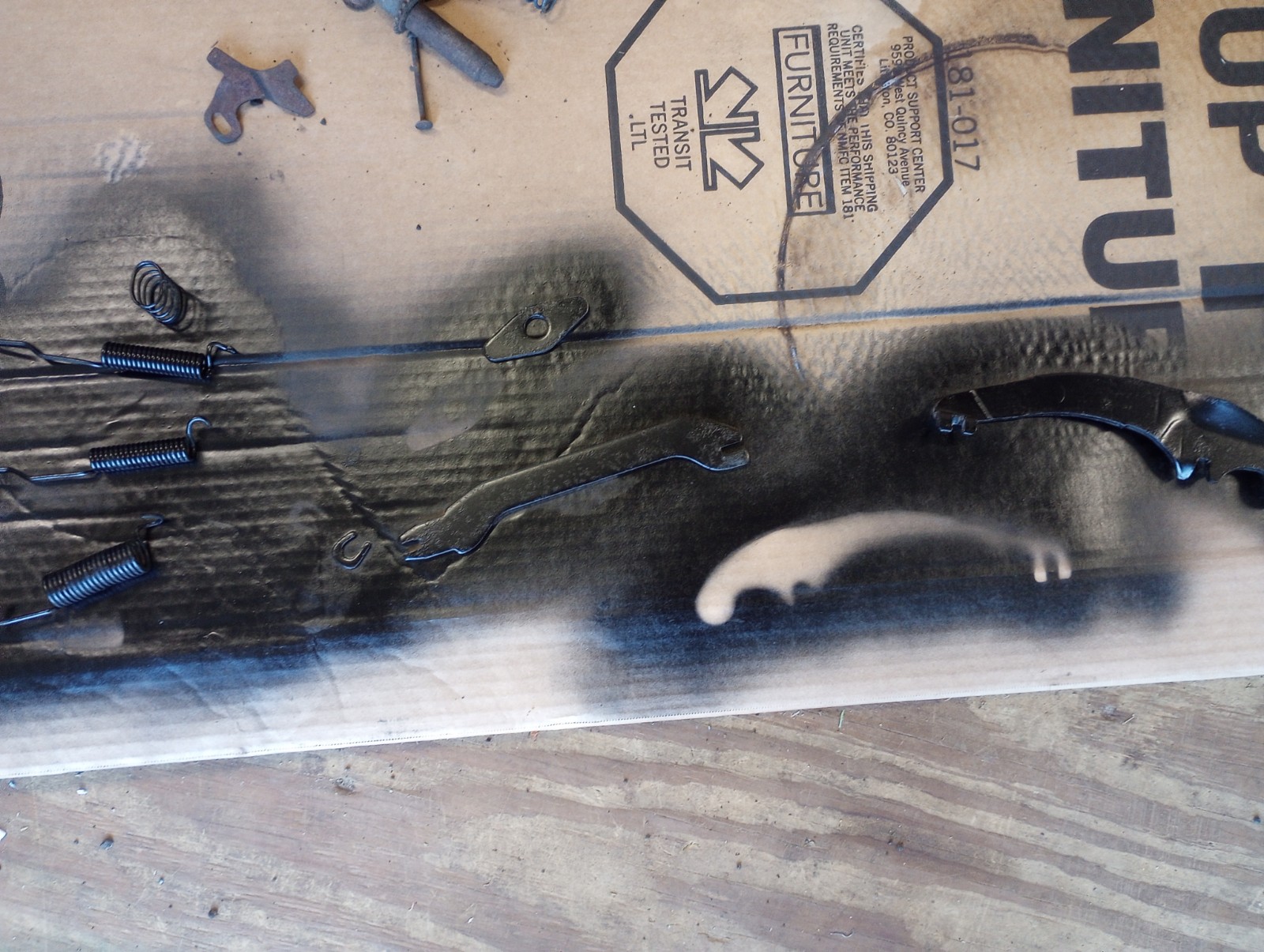
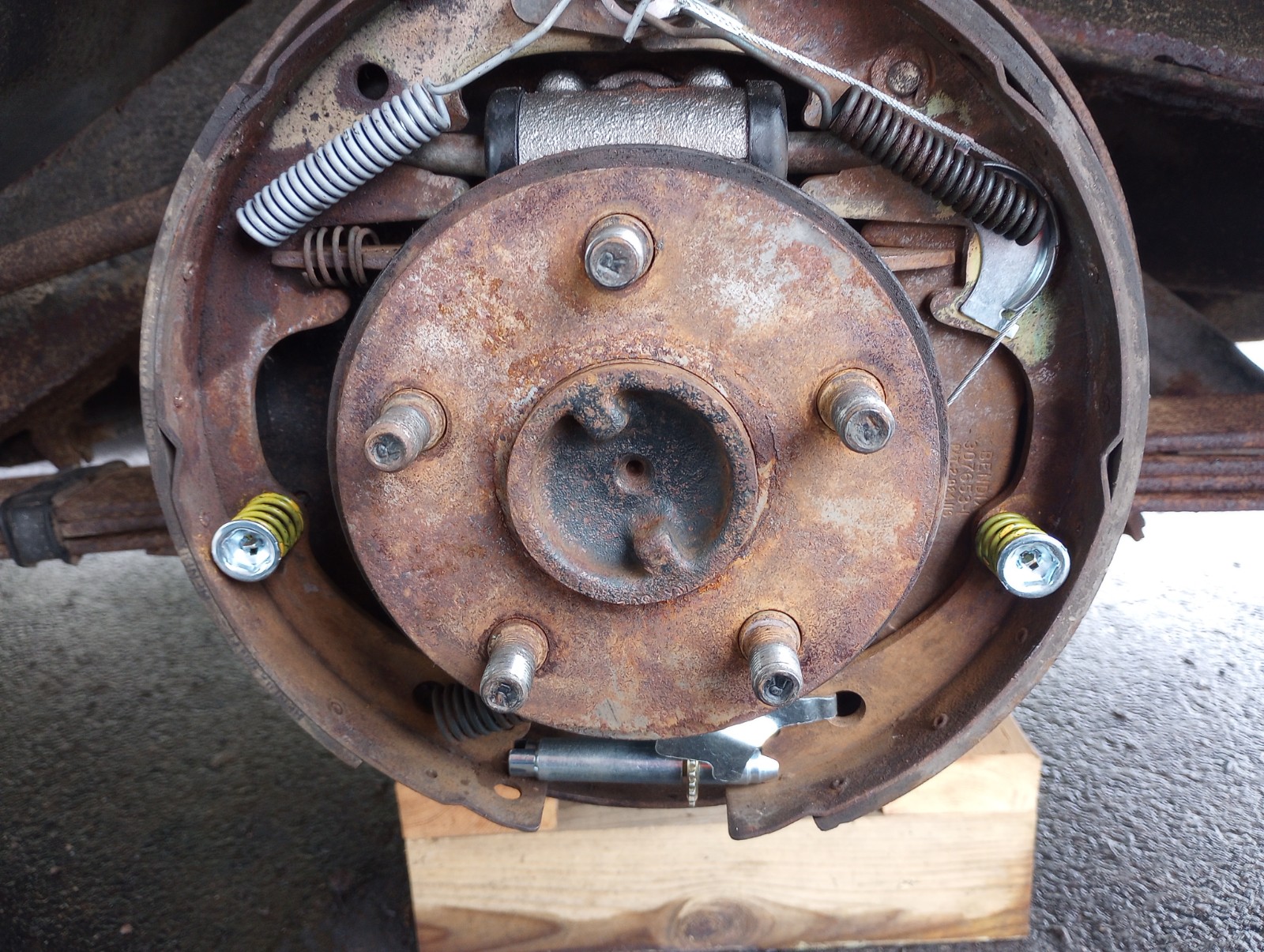
One rear brake complete the correct way - cleaned and painted w/ caliper paint. The other brake parts are sitting in my tub of Evapo-rust along w/ the hinges from my glove box.


-
On 4/8/2023 at 8:37 AM, SCPO-PD said:
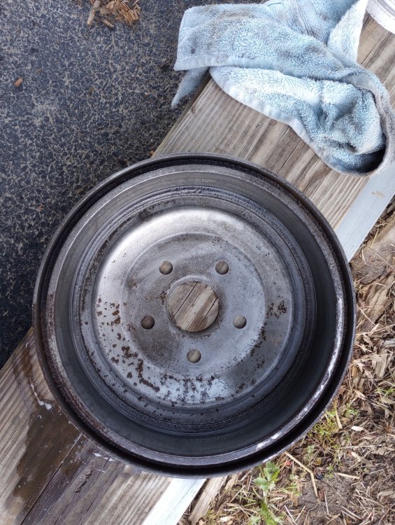
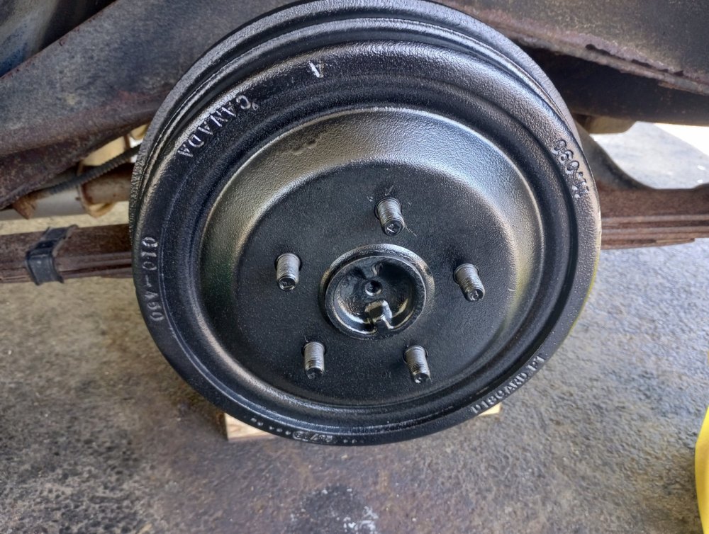
Well - I had a chance to dive into the Rear Brake Re-work... I got the driver side complete this evening. Things went well - Especially considering I haven't reworked drum brakes in close to 30 yrs..... I need to clean the drum and paint it but not today as it is raining. I did brake the brake line going into the cylinder but no worries as I had a new one purchased and ready to go.

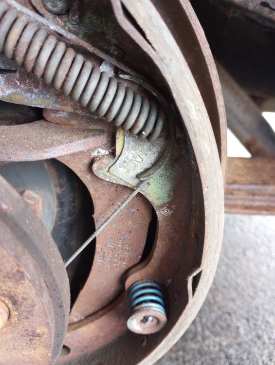
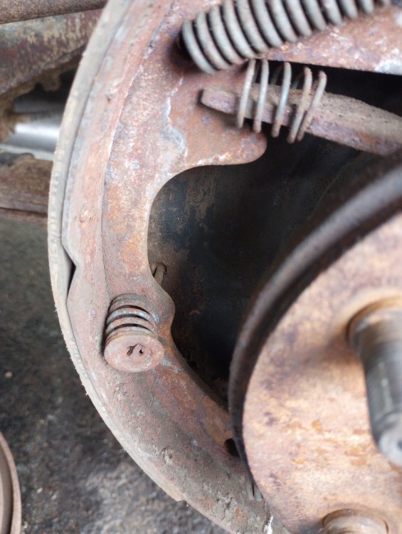

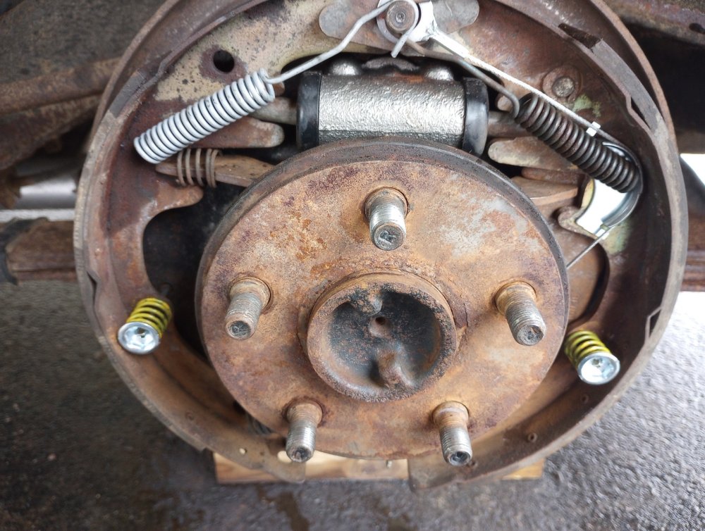

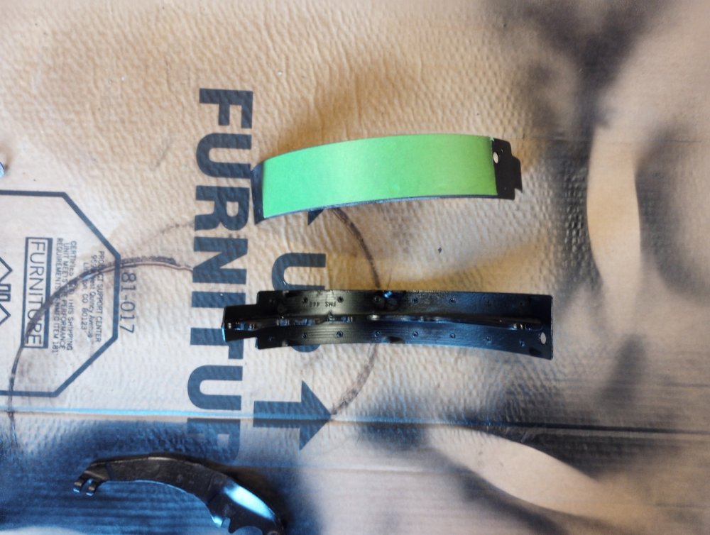
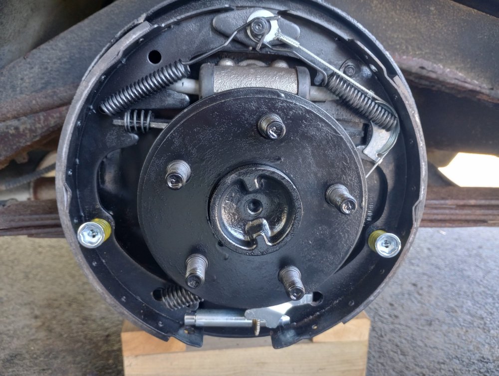
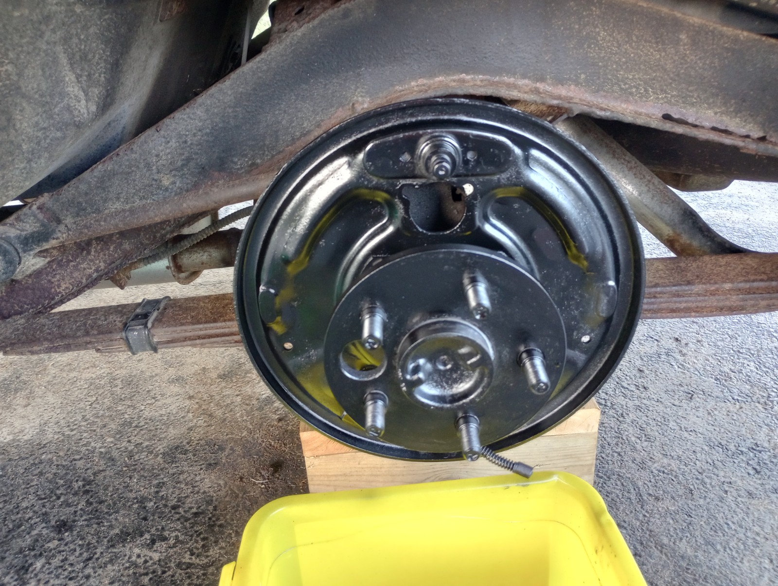
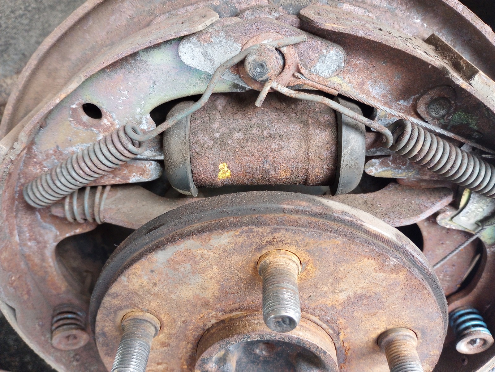
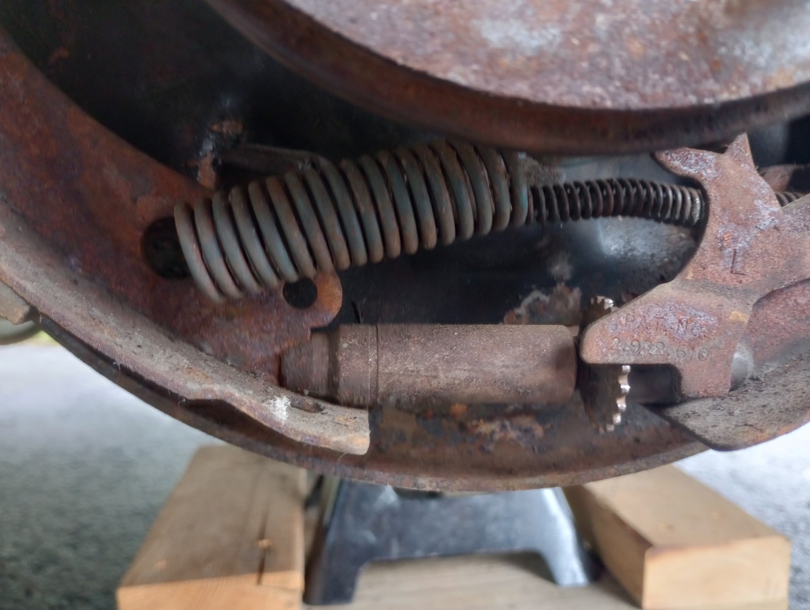
I'm aware of your time crunch, but while you have the brakes open, do take the opportunity to wire wheel all the bits and apply a coat of paint if you can. Did this about 6 months ago and it only takes about half an hour per side (including the Backing Plate whilst still on the Axle and 1/4" flange spacer). You'll be glad you did ! I use a combination of pedestal grinder mounted 8" wire wheel and another in a 4" angle grinder and can vouch for their effectiveness. Phosphating also helps.


.JPG.8a315bb77ff0486353e3596c5b71751d.JPG)


Identify the automatic transmission
in 1965-83 Avanti
Posted
Hi Kodjo- Do read the story here, https://www.studebaker-info.org/Tech/Transmission/FMX/fmx2.html
it will answer some of your questions. A quote from the text is as follows....
"The transmission used in the Studebaker Avantis is called a Powershift', which is basically the same as the FlightOmatic, except the shift quadrant and valve body are different (PNDLR vs PNRD21) and it had more clutches and a larger HD front drum. It was manufactured by Borg-Warner and is described in the Stude shop Manual as an 'AS n-10', with the 'n' differing between applications. The transmission was carried through to the Avanti II and is called an FMX, however the torque converter and bell housing are unique to the Avanti II, in that it is mated to a GM engine.
I wrote a blog on the overhaul of the Studebaker type 8 small case Transmissions and went to the trouble to measure seals and bearings along the way, and I believe the Rear Extension Seal equivalent to be a Timken 410059. The original was marked ‘Victor’ 49567.
Hope this helps, some.