

grant mills
-
Posts
56 -
Joined
-
Last visited
Recent Profile Visitors
1,014 profile views


grant mills's Achievements
")


-
I can only give my experience. Many years back (after discovering my speedo read 10% higher dues to small michelins) I replaced them with 225/70-15 (on Dayton wire wheels) to get the speedo back up to within 1% of an accurate reading. The front tires experienced rubbing from the inner fender well when I did fast sharp corners (is there any other way to take a corner?) I switched the front to 225/60 and the rubbing stopped (plus it added to the rake of the vehicle) Since I replace the front coil springs, the front sits high enough that I could use 225/70 all round. But I had gone back to the original sized tire for the Avanti of 205/75 at my last tire replacement.
-
It is great to see the start of a restoration with fresh and newly painted parts ready for installation. I also have a question that I posted elsewhere but still don't have an answer for. Would you be able to tell me the height of the arc of rear leaf springs? That is, with the spring ends sitting on the ground, curve up, what is the distance from the center (connection point to frame) to the ground? I would like to replace the current "flat" springs on my 1984, and there is a spring manufacturer close enough that will build them to specs..all of which I have except for the uninstalled height of the leaf spring. I know that EatonDetroitSpring has them, but It would be double the cost of a local manufacturer after Canadian $ exchange and shipping.
-
what are the symptoms? Is it hard to turn the steering wheel to get any tire movement? Does the steering jerk hard in the direction that you turn? Have you checked the lines between the pump, control valve and cylinder to make sure there are no kinks. When replacing the control valve seals did you get the new seals oriented on the valve correctly? Could you have switched the lines between the ports on the components? Are there any leaks around any of the components? I know that you were careful in your work, but until you check these out, none of the rest of us can help you...for example when putting the cap back on the end of the control valve, did you get the set screw back to its original position? Could the new pump be bad? Please give us something more to go on than it is not working at all.
-
should I add grease zerks to the front sway bar supports?
grant mills replied to grant mills's topic in 1984-91 Avanti
To recap my experience. (I gave it in another posting) Loosely Install the two end brackets with bushings. Slide the sway bar into one end until it extends out the end. Next slide the other end into the other side and adjust so each have about the same amount in the bushings. The ends of the bar will be about 1/2 inch inside the bushings. Now raise the center of the bar and support it just below the final location. The inside bushings should have been in place before sliding the ends into the outside bushings. Loosely put the tabs for the upper supports in to their slots and raise the center support to hold the brackets in place. I used a bell jack to push a support bracket up until the bolt can be put through the bracket and frame support hole then loosely bolted them together. Do the same thing for the other bracket and then tighten all four brackets. -
About 30 years ago, my local garage/dealer sent the power steering cylinder to a local shop to have the shaft re-chromed. It started to leak again after the last 10 years of non-use and I ordered a rebuild kit....did the replacement myself and no more leaks. If the shaft of the cylinder shows any signs of pitting, you will need to replace the cylinder or get the shaft re-chromed..otherwise the rebuild kit should stop any leaks there.
-
should I add grease zerks to the front sway bar supports?
grant mills replied to grant mills's topic in 1984-91 Avanti
I heard the same thing (from Dan Booth) but since the outer edges of the bushings have a lip that the support brackets sit inside, I am not worried about the bushings walking out. -
I am about to reassemble the front sway bar after having the coil springs replaced. All the supports for the bushings have a 1/4" in hole (un-threaded). Would it be wise to add zerk grease fittings to these holes? My alternative is to occasionally spray some lithium grease around the sides of the bushings. (the bushings are rubber) If I do put grease fittings on...should I drill a hole through the rubber down to the bar or just grease around the inside of the supports?
-
I am having a problem with the new front springs. They do not sit perfectly vertical.....At the top (the pocket of the frame) the spring is pushed to the side of the pocket resulting in major noise from metal on metal movement, whenever I hit a small bump. The opposite side of the pocket has about 1-1.5 inches of clearance. The shop that installed said that the top of the spring is centred in the pocket and then looked for solutions including rotating the springs, but indicated that it would only move the contact point to a different spot on the pocket. The base of the spring has a tangential end which may be causing it to slide to one side on the base support. Do I have the wrong base type for the application (should it be square)? Is there a base plate that could centre the base of the spring? Should I simply get a pair of springs from one of the vendors and replace these (new) ones? Would a new set of springs have the same problem? Enquiring minds and all that!
-
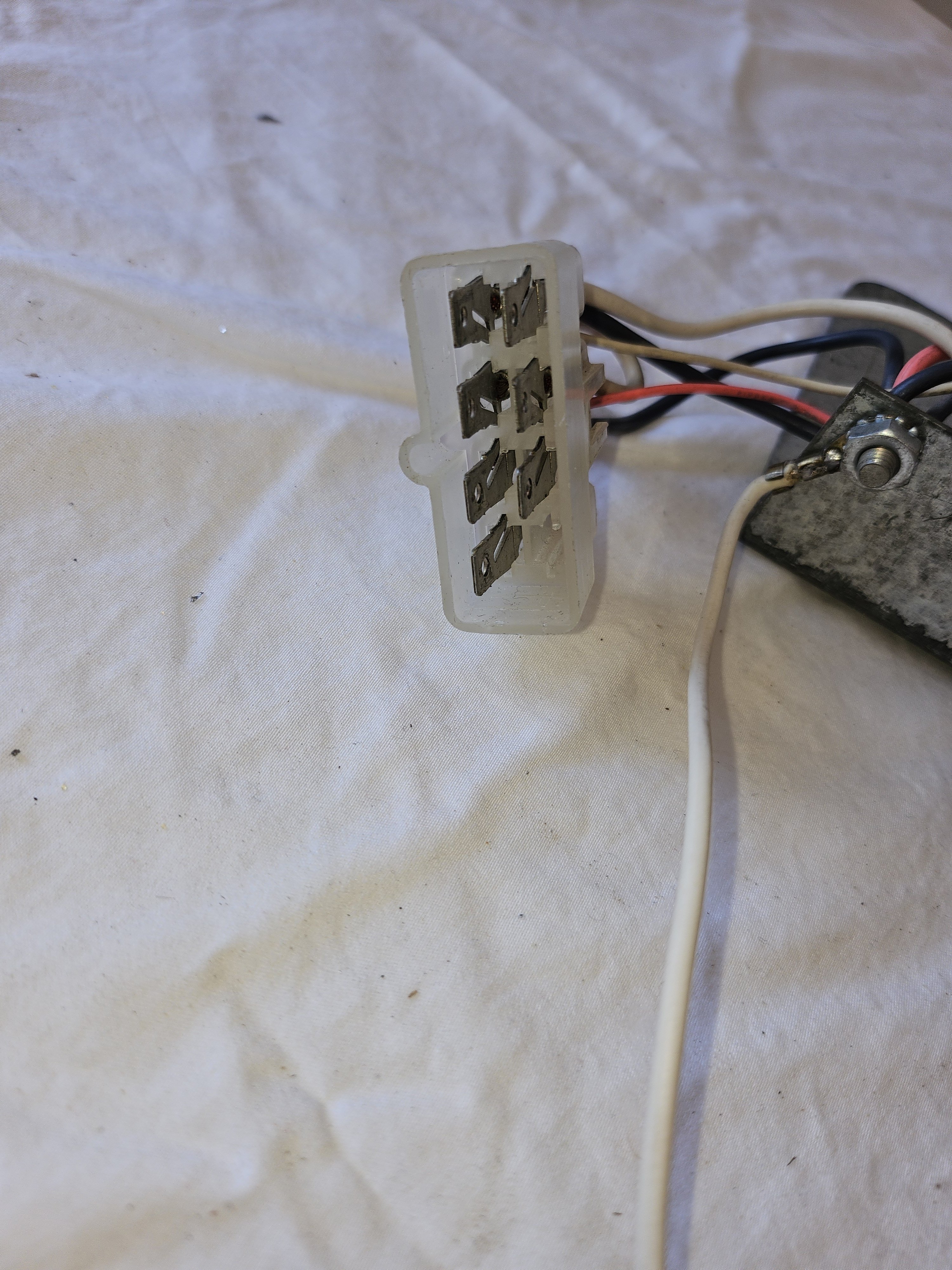
Solved (partially) It is part of the electrical control for the SkyTop power moonroof. When I put the new radio in, I found that my moonroof was dead. I finally traced it back to the above part. It seems that when I reconnected everything, I failed to fully connect that 7 pin connector. (Big hands, small opening, tight sockets) When I went back into the dash, I noticed that while the two connectors were joined, they were were only held in place by the friction of the plastic covers, but not seated. Fully seating the plugs restored the moonroof to operational.
-
I replaced the bushings on my car last year. On my '84, the rear sway bar is larger than the earlier ones (3/4" vs 1/2) . The square bushings I was originally sent (from Avanti Parts and Restoration) were too small and when I contacted the seller about this, they sent me larger replacements which they said were from the front sway bar but fit the rear properly.
-
Built in Nov 82, what is the HP rating of my 1983 Avanti
grant mills replied to forward's topic in 1965-83 Avanti
I believe that the 305 used in the Avantis were all L69 engines putting out 190 H.P. I do not know if AMC ever used the corvette L83 engine in an Avanti. -
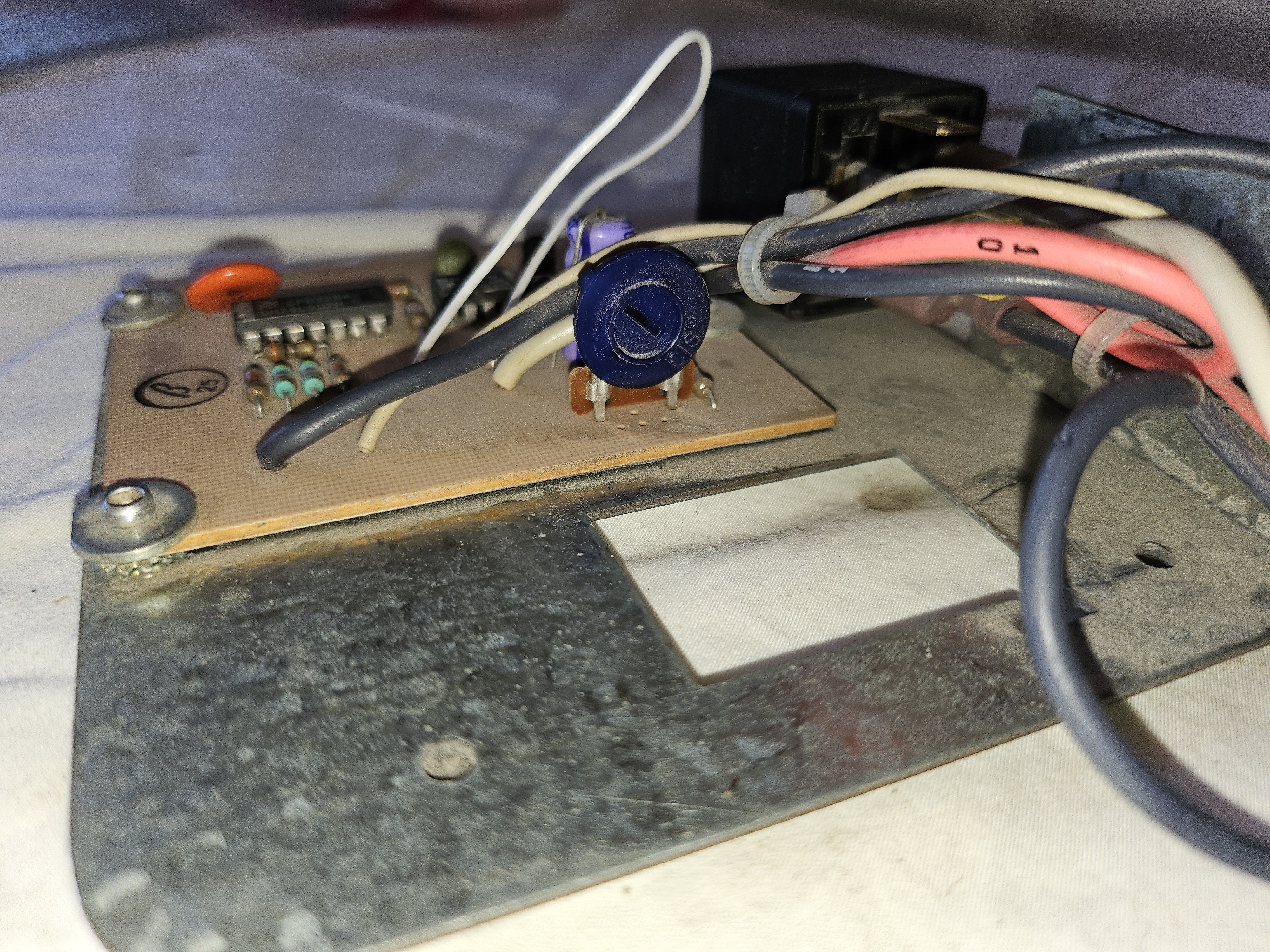
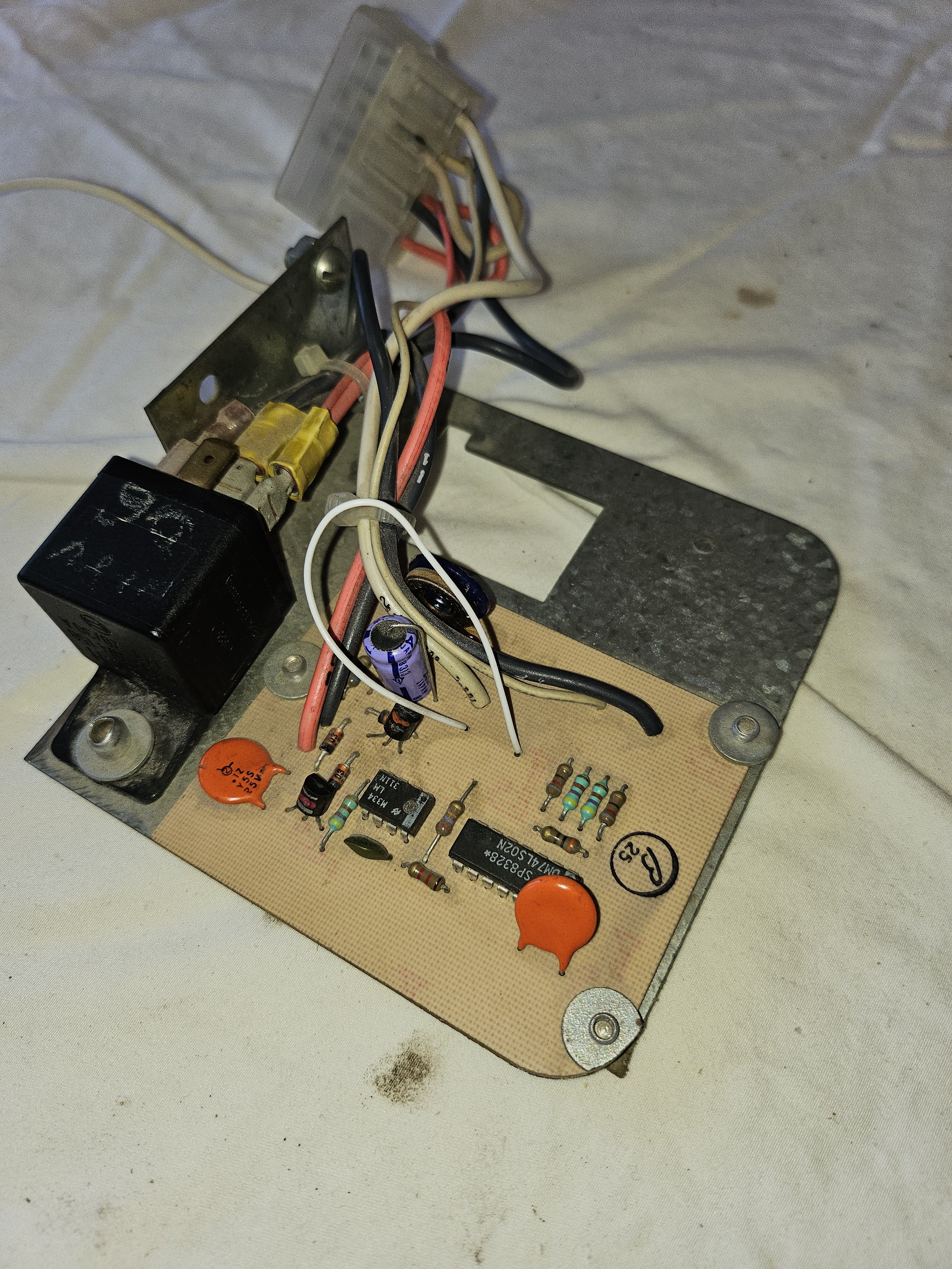
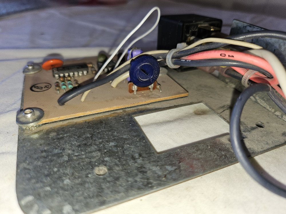
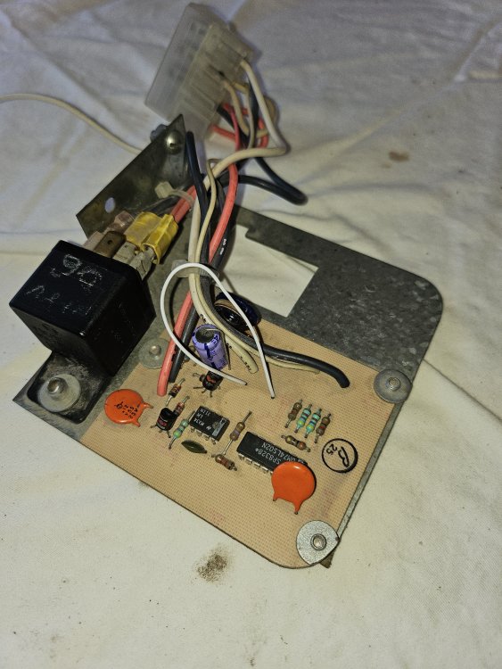
In my previous query about radio upgrade, I asked about a part that sat on top of the old radio and was connected to an under dash harness (NOT to the radio amp output) I have not heard any explanation for the part. Its base is 4.25" square. There is a trim-able pot. as shown in the first picture and the connector to the under dash harness in the third. The only connection to the old radio itself was a ground wire connected to the rear support strap of the radio. Does anyone have any idea what the purpose is of this simple PCB. What might it control/support? (Aside: I have installed a "RetroSound" replacement and it fits like a glove in the old opening....I only have to memorise 18 pages of control options/settings)

-
Above the interior rear view mirror (front centre ceiling)
-
84 Blaupunkt sacramento radio removal...help needed
grant mills replied to grant mills's topic in Avanti Information
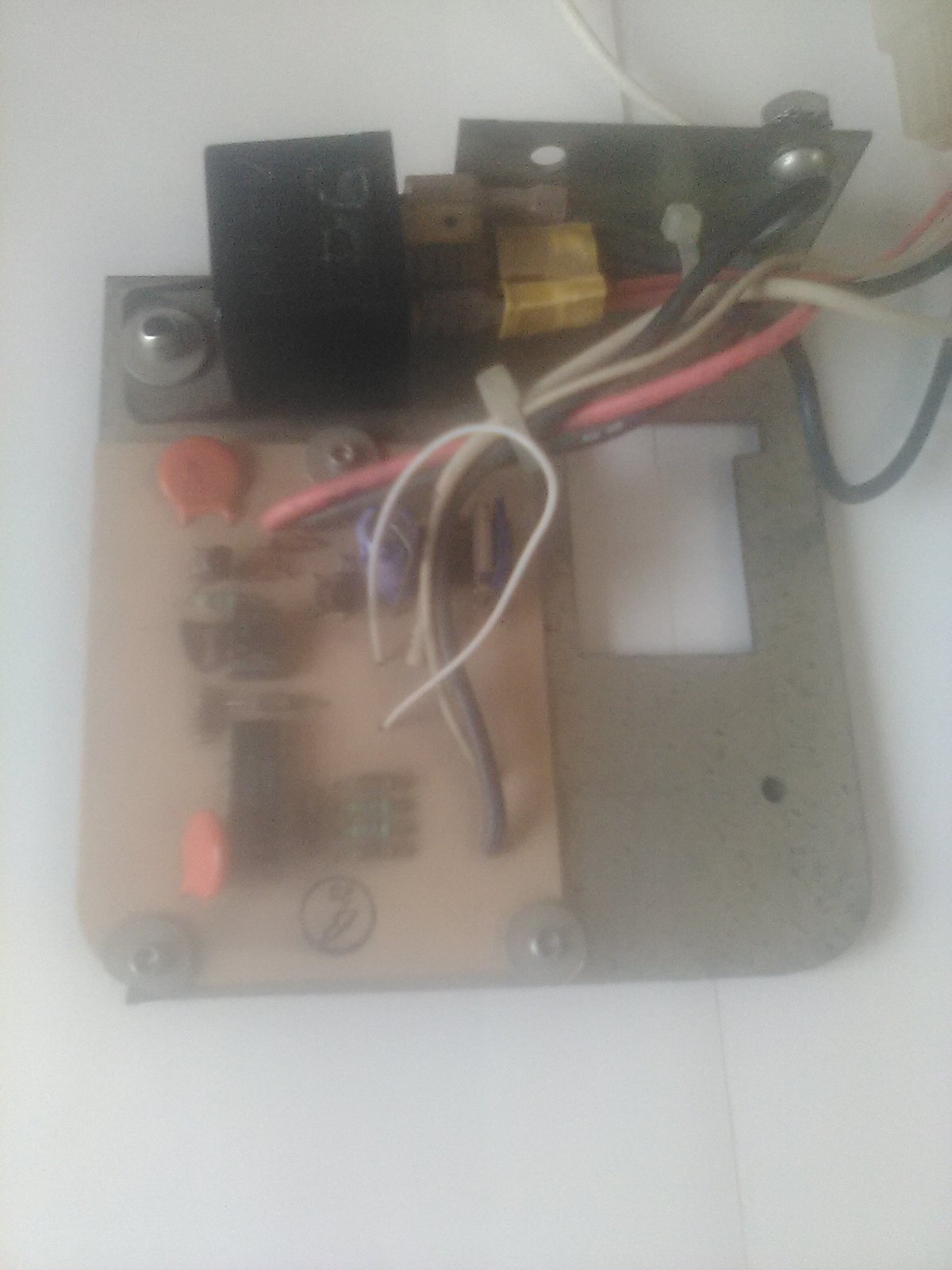
We may be talking about different items. I've attached a picture of the PCB that sits on the radio...apologies for the poor quality, but my cheap flip phone has a cheap camera.. Anyway, I did a continuity tests between 3 of the speaker wire connectors (Becker 2pin DIN) and the each of the 9 pins on the connector to the "amp". I got nothing. I would expect an external amp to be connected to the AUX output (round 7 pin connection plug) and that had no connection. So I am still curious as to what it is for (on my system)
-
While the door panels are easy to remove and put back on, repeated re-screwing can make the connection into the fibreglass loose. After much work on my doors (and some stripping of the fibreglass interior door panels) , I ended up enlarging the holes, squaring out the circle and placing plastic (locking) inserts that would accept the screws. This made the panel more secure against the door