


Parklife
-
Posts
16 -
Joined
-
Last visited
Content Type
Profiles
Forums
Events
Posts posted by Parklife
-
-
Glad to help! 🙂
-
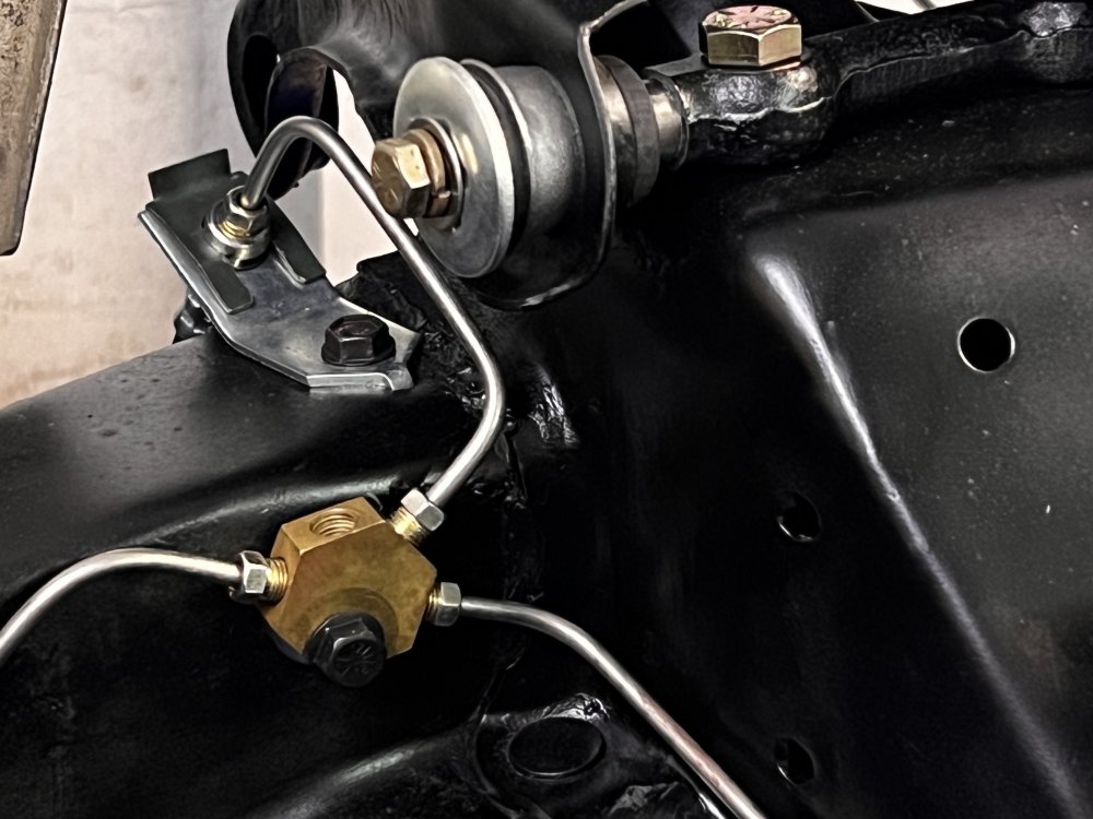
If you're referring to the brass hexagonal block that the master cylinder and all the brake lines attach to, it's mounted on the inside of the frame rail, slightly behind the front suspension crossmember, and it's held in place with a 5/16-18 bolt, and there should be threads cut into the frame. If you're missing it, there's about a 3/16" thick washer between the block and the frame to space it off slightly.

-
15 hours ago, Leo B said:
How about upper one? Same problem? Should be same thread. 1.134 - 1.136
The uppers were a much tighter fit - just large enough for the tip of the caps to pilot in, but they required cranking them in the rest of the way with some determination. The bores on those were 0.020" to 0.030" smaller diameter than the lower control arms.
The lowers, well, that's a story. The first set - the originals on the car - were slightly bent. The second set were NOS replacements, that FedEx managed to lose somewhere as they transited through Portland. This is the third set. But now needing a fourth set? I'm getting a real black-cat, Friday the 13th kind of feeling from this. The universe wants this car off the road and is prepared to do everything in its power to make it happen.At any rate, thank you everyone for reassuring me that I haven't lost my mind. Perhaps about other things, but definitely not about this, at least.
-
Correct me if I'm wrong here, but the purpose of coarsely-threaded caps that retain the lower pin into the control arm is that they're supposed to thread themselves into the steel of the lower control arms, so that when they're tightened up the caps have torqued up to the control arm, thus allowing the center pin to turn freely inside.
If I have my understanding correct, then there's no way this - on a set of NOS control arms with no threading in them whatsoever - should happen?
The ID of the bore on the control arms is 1.140" using my $8 Amazon digital caliper, while the OD of the threads ~1.136", giving me a nice four-thousandths slip-fit.
-
New York
-
17 hours ago, brad said:
What year is your Avanti? Later cars in the 80s had the type you show that was on your car. They are a bear to curve properly to fit well.
It's an early '63 - it looks like the car was last restored in '93 so that makes sense that the later trim pieces may still have been available NOS at the time.
-
-
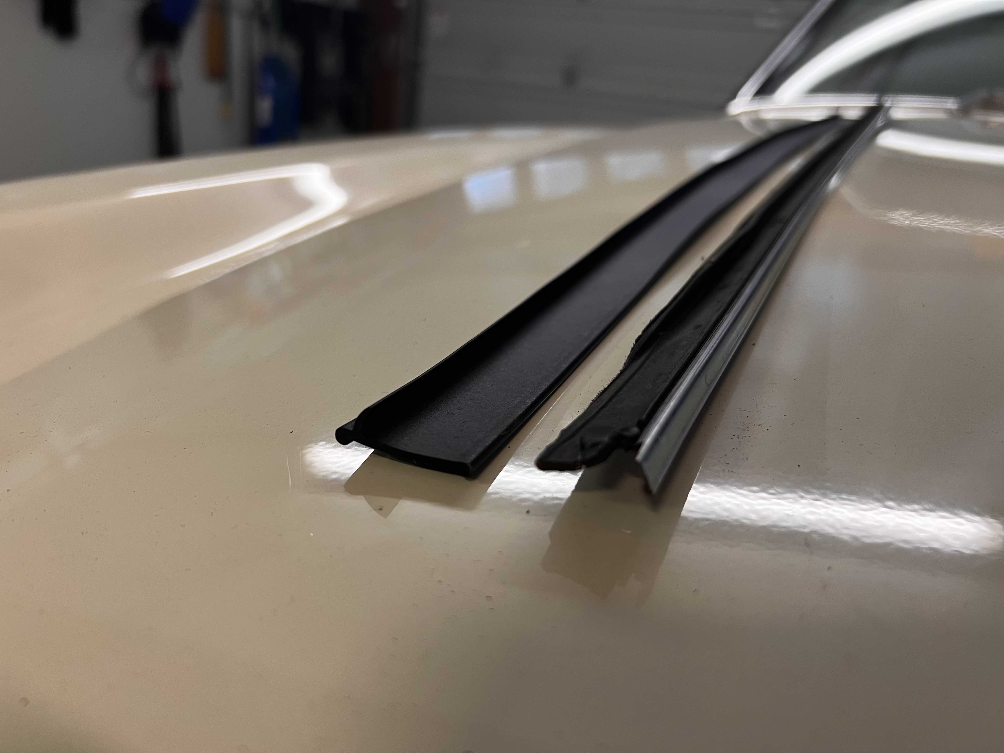
A part of me knows the answer to this already and is afraid to ask, but:
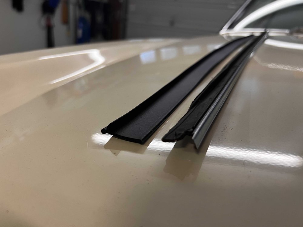
While attempting to replace the outer window weather seals, I'm noticing that the trim on my car is one molded piece — just a thin strip of metal with some flocked rubber molded on top of it. All the instructions say to remove the old weatherstrip rubber from a stainless-steel channel and slide in the new ones, but there's the rub: With the pieces on the car, there are no channels for the replacement weatherstrips to slide into, nor clips that were holding the trim in place. The replacement rubber piece is on the left, the trim that was installed on my car on the right. They're not even the same width:
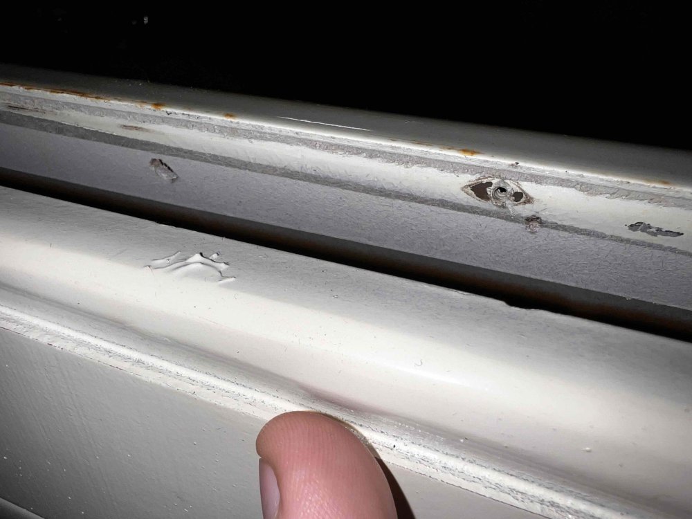
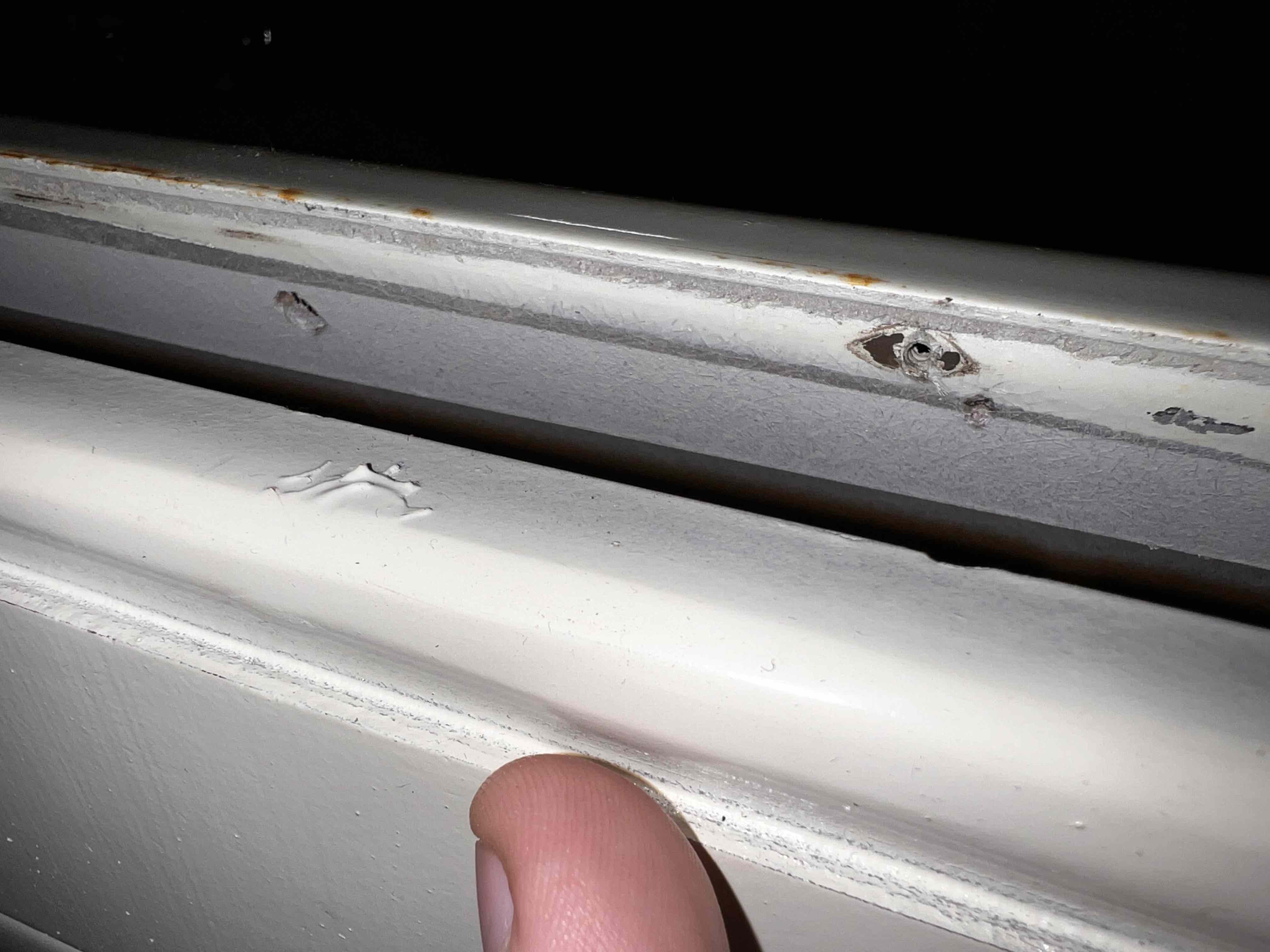
This suspicion I have — that I'm not dealing with the correct pieces on my car — is doubly borne out by the way the trim is attached to the door. There appear to be four large, perhaps 8mm or so, holes in the door. From my understanding, there should be four push-in clips that retain the stainless weatherstrip frame to the door using these holes, and one screw holding it in place at the end. As you can see in the next picture, none of those were used on my car. Instead, it has tiny holes drilled into the door frame where teeny self-tapping flathead screws were used instead:
Correct me if I'm wrong, but it does appear that what I ended up with on my car are something entirely different that the previous owner just kind of slapdash adapted to fit an Avanti door, right?
It appears that I'll need a pair of the original Avanti weatherstrip channels. Which leads me to my next question, then: Does anyone have a pair of the original weatherstrip channels they would like to sell, or suggestions as to what could be substituted as an assembly to replace them? The rubber, as you can see above, has cracked and torn off in several places so I can't even feign ignorance and put the old ones back in.
-
Hi @Kodjo, unfortunately I already sent out the extras I had.

-
All spoken for. Thanks, folks!
-
-
You got it, Jim. I'm stopping by the post office this evening so I'll message you with the tracking number once it gets issued.
Wes
-
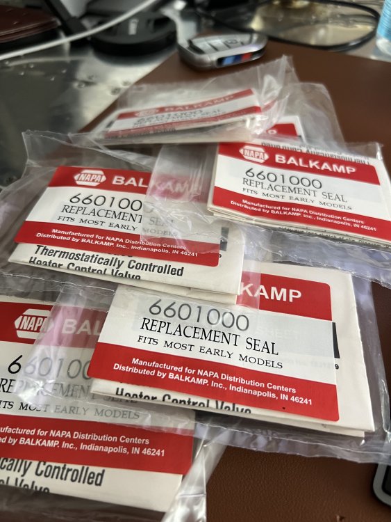
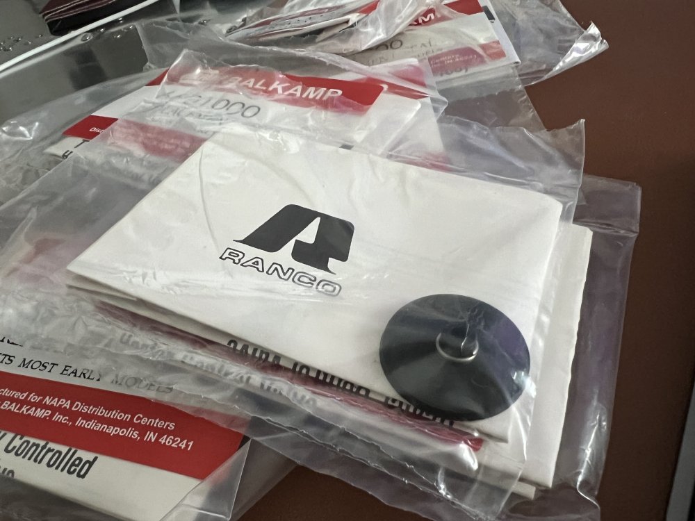
Whoever pulled the single NAPA 660-1000 heater valve repair kit that I'd ordered managed to pull a box of 10 and ship that to me instead. I have seven left that I have no need for, as I already have one problem-child Avanti. So if anybody wants one, please send me a message and I'll drop one in the mail, gratis.
Thanks!Wes


-
@rufcar - as luck would have it, I ordered one (one, singular) 660-1000 from NAPA, and whoever picked/shipped the part ended up sending me a box of 10. These are all the expected Ranco HTR-100 kits in each bag with the instruction sheet and the rubber seal. Send me a message with your address and I'll drop one in the mail.
-
I just happen to have a power window relay sitting on my desk while reading this, so hopefully this helps. Your underhood PW circuit will have two components to it - a circuit breaker that's designed to trip over 20A and reset when it cools back down, and a relay that switches power on and off to the power window circuit when the key is on. (Note: I have an early '63, your wiring might have some slight differences.)
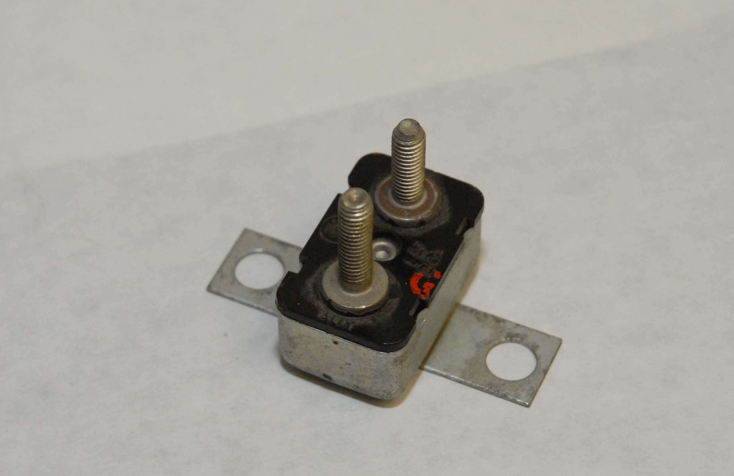
The Circuit Breaker
Like you guessed, the two-wire box under the relay is a circuit breaker. One side connects to the starter solenoid so it has a good, high-amp source of B+, and the other side connects to the PW relay. It should look something like this.
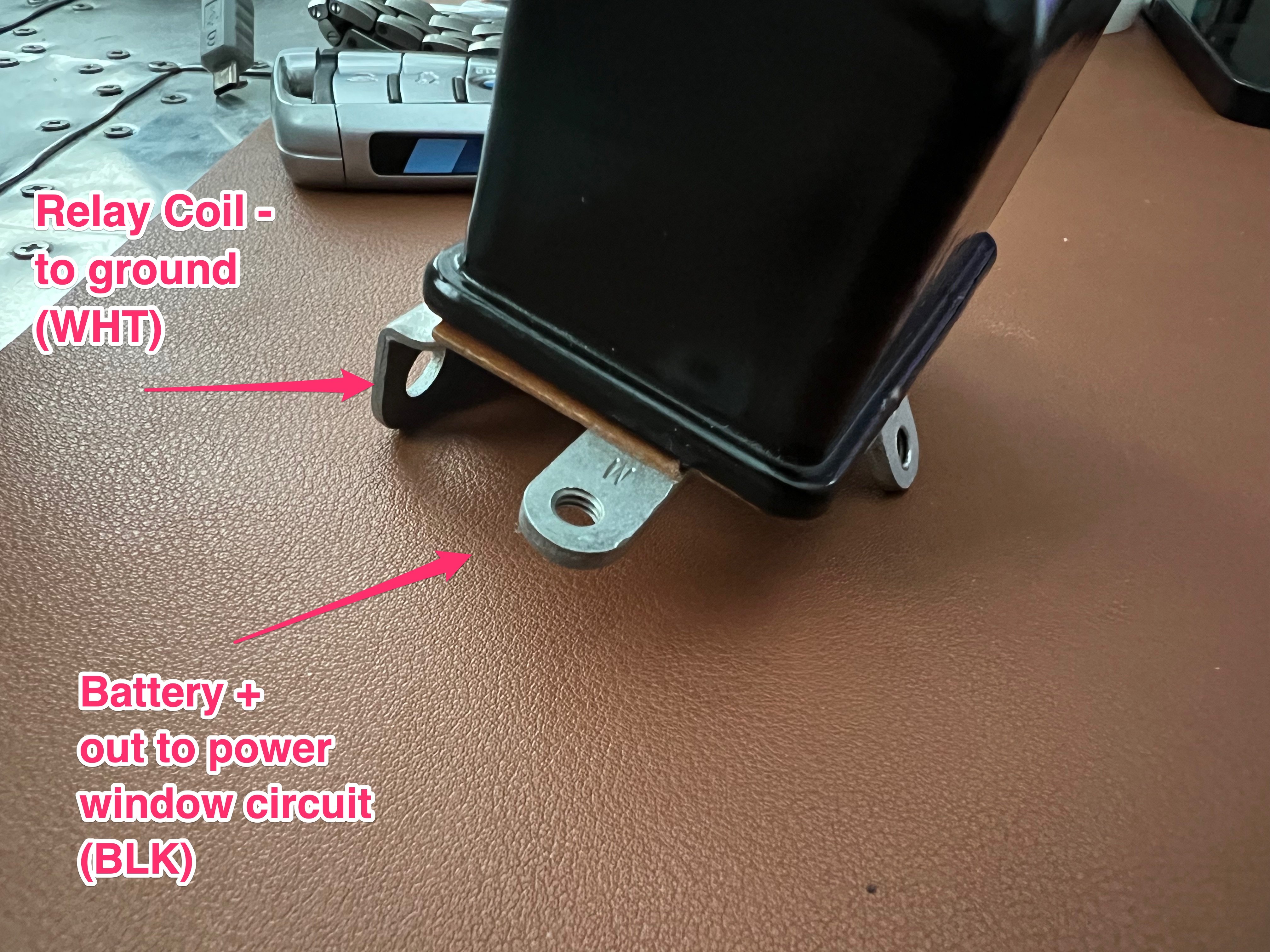
The Power Window Relay
Every relay is going to have at least four connections - one to supply power and one to ground the relay coil, one that supplies the higher-power source that needs to be switched by the relay, and one that is the output of the relay to the circuit being switched. I've attached pictures of (from what I understand, original) relay here. The four connections are:- IGN is the source of key-on power that energizes the relay coil. On my '63 this is connected to the voltage regulator about a foot away and is yellow with a black stripe. It's my understanding that later Avantis changed this so the power window relay is energized when the key is in 'accessory' instead of just 'on', so your '64 may be different
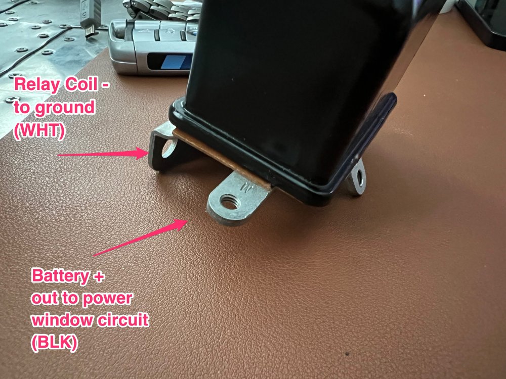
- Ground is done through the frame of the relay. Being a fiberglass body, there will be a white wire connected to the bracket that mounts the relay, and that white wire is what provides the ground for the relay coil. With both IGN and Ground connected, you can make the relay energize and click - you'll hear the coil sucking the contacts closed inside the relay can
- B is the high-amp power source that the relay is switching. The other side of the circuit breaker is what supplies power to this terminal. On my car this is black.
- W is output from the relay to the power window circuit of the car. This is also black on my car.
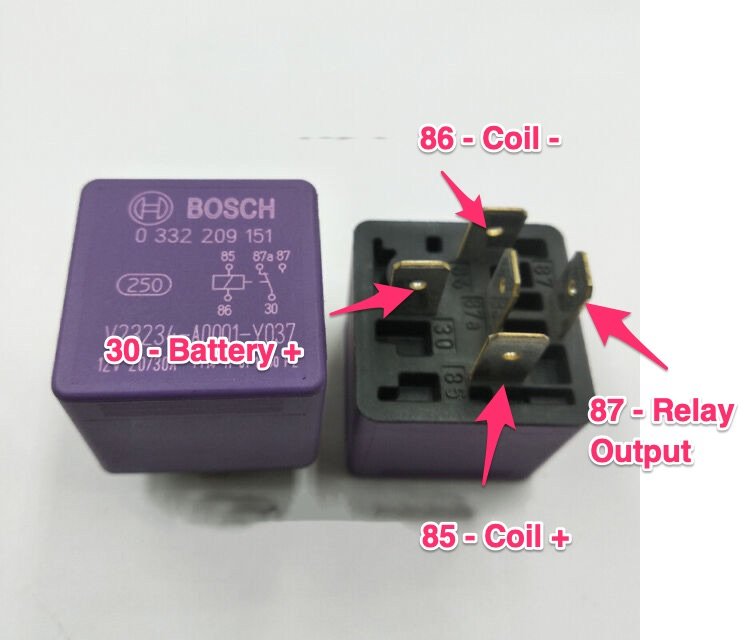
So for any of those replacement relays posted, the three terminals will be IGN, B, and W. The mounting bracket of any of those relays will be the ground for the relay coil. Hopefully the replacement relays come with a diagram showing the pinouts, so you can tell which is the coil positive connection and which two will be the switched terminals.
Alternatively, you can find some nice Bosch-style relays that can switch up to 30A and use a standardized pin-out, which has become the de facto standard for automotive relays for the last 40 years. If you do, the wiring for those I've attached also.
Best of luck!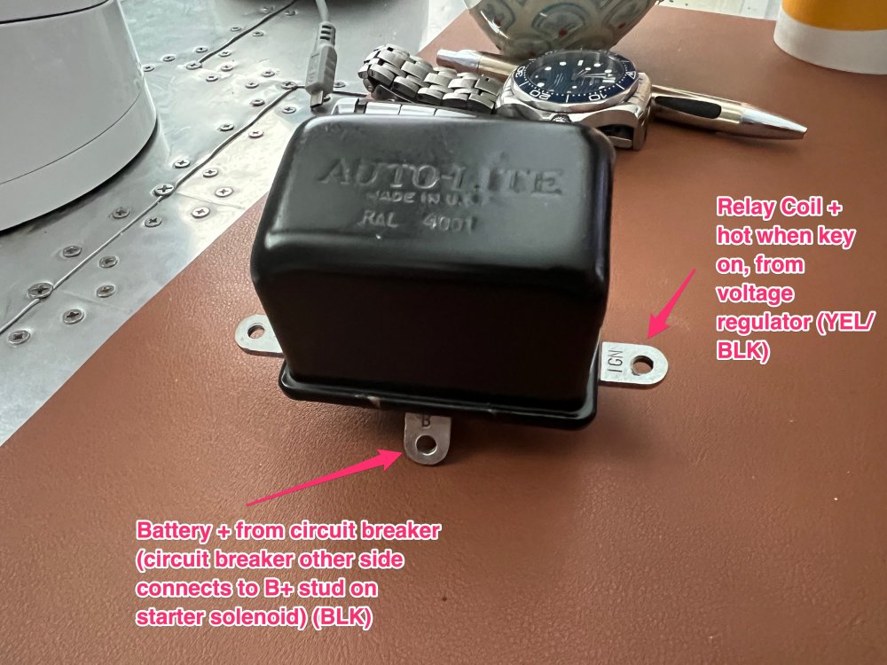


1963 Avanti R2 4 Speed For Sale
in Avanti's For Sale
Posted · Edited by Parklife
Typos. Eye thank god four spell cheque.
Tentatively sold! Thanks for looking.
THEN:
NOW:
I have to start by telling you that my entire existence could be summed up in one phrase, and that is: If my life wasn’t funny it would just be true, and that is unacceptable.
What that really means, other than what it sounds like, is, let’s say something happens and from a certain slant maybe it’s tragic, even a little bit shocking. Then time passes and you go to the funny slant, and now that very same thing can no longer do you any harm.
So what we’re really talking about, then, is the 1963 Studebaker Avanti pictured above.
THE TRAGEDY
Now, I've looked everywhere, and I'll be damned if I can find it, but I know I read this passage somewhere — I think in Kerouac — but I can't locate it now, so you'll just have to go along with me that it's there. It's a scene in which a young supplicant, an aspiring poet, somebody like that, seeks out this knowledgeable old philosopher — kind of a Bukowski or Henry Miller figure — and the kid comes to the old guru in his ratty apartment, and he sorta kinda asks him that old saw about the meaning of life.
The old man purses his lips and beetles his brow; he perceives the kid is really serious about this; it's not just jerk-off time. So he nods sagely, and clasps his hands behind his back, and he walks to the window and stares out at the deep city for a while, just sorta kinda ponders for a while. And finally, he turns to the kid and he says, with core seriousness, "You know, there's a lotta bastards out there."
I doubt that the Oxford Encyclopedia of Philosophy will ever crib from my notes, but I kinda forgot that truth and, demonstrating too much trust and innocence, paid $60,140 (yes, sixty grand) for this particular Avanti, 63R-1358, in March of 2022. Only an idiot would have paid that much for something without first, I don't know, taking it around the block? Guess whose name was in the envelope in the category of Most Outstanding Performance by an Idiot? You get one attempt, but I don't think you'll need more than that.
In my defense here, take a look at the pictures from the selling dealer: https://drive.google.com/drive/folders/1x8JMa8f9XQMs3va2exzBdkCIwvTwNqZZ?usp=drive_link Play the YouTube video. Marvel at how complete and lovely it appears to be. Close your eyes, like I did, and see it with vision. See yourself cruising down 132nd Street in Redmond, underneath the canopy of trees, on a perfect summer evening. Hear the burble of the exhaust, feel the _snick_ of the shifter in your hand. Then snap yourself out of it and remember that you're looking at pictures and they tell you precisely f**k-all about the actual condition of the car. Dealers are counting on this. Dealers will do everything possible to make those pictures look good. They will, for instance, paint over the underside of the car in black truck-bed liner that covers rust and - more critically - oil leaks. They'll spray the exhaust system with silver Krylon. They'll brush over everything rusty under the hood with dark gray enamel to make it look like sleek new cast iron. They'll spray the calcified salmon-orange heater hoses — the kind that NAPA used to sell by the foot, long since hardened into something that is rubber in name only — with gloss black to make them look supple. In short, dealers are an aging, overweight hooker cynically spreading her legs and offering her rotten prize to another generation of shaking, guilt-ridden adolescents who don't know better. And they'll do anything to just this side of provable fraud to separate you from your dollars.
There's a lotta bastards out there.
THE SHOCK
It should have been a sign when the transport driver couldn't actually start the car. It was delivered on the top rack of an enclosed transport, and the only way he could get the it to move was to lean on the starter and then, while it was cranking — cranking but not, more critically, starting — pop the clutch out. My heart fell like a bowl of goldfish smashing onto a cathedral floor. After five minutes of cranking and pumping the gas pedal, I got it to start and pulled it into the garage. That evening I sent a message to a friend of mine: "I think I just bought a sixty-thousand-dollar shitbox." His response? "Dude, there will always be issues. Get up early tomorrow morning, drive it to get coffee, then sit outside while looking at it and reflect on how you finally bought your dream car."
A brake line split overnight and emptied its molasses-thick fluid all over the garage floor. I haven't driven it more than those fifty feet the first day. I still got coffee, but took my X5 instead.
I should have cut my losses and sold it there, but as I am not primarily a smart man it took me a year and around another $30,000 in parts to finally say to myself Wes... you has fallen down a rabbit hole, kiddo. What I'm saying is that I don't always have a good sense of when to walk away. Perhaps a moving finger writing mene mene tekel in letters of fire on the garage wall would have gotten the point across.
The cascading list of the poor car's ailing condition is exhaustive. It can also, mercifully, be summed up in chapters; just like the Studebaker service manual. Or a James Michener novel. Your pick.
BRAKES
Braking, on the car, was a theoretical concept. Everything sat for the better part of 30 years and, as you'd expect, water pooled in the lowest parts of the braking system. The lines were rotted from the inside out. Wheel cylinders were frozen. The less said about the condition of the front calipers and hoses, the better. The parking brake? Actually pulling the handle to try it was a land where angels feared to tread.
All the hard lines on the car were replaced with a new pre-bent stainless steel set. All hoses and retaining clips are new.
The rear backing plates were taken to bare metal, primed, and painted. Shoes, wheel cylinders, springs, and retaining clips are new. The parking brake arms and bar and brake adjuster eccentrics and nuts were sandblasted and refinished in yellow-chromated zinc. The original drums were scored and have been replaced with new finned drums and new hubs and studs, since I had no desire to try unstaking the studs and hubs from the old drums. New rear axle oil seals are installed.
The rear parking brake cable is installed and is new. The parking brake cable guides on the frame have been stripped and and refinished in yellow-chromated zinc. A new front cable is uninstalled but included. The parking-brake hardware at connects the cables has also been replated and is uninstalled. The parking brake handle has been re-plated as it was rusted in place in its tube. The tube has been cleaned and repainted. A new pawl and spring are included.
Up front, the booster was sent to SI and rebuilt. Included is a new single-circuit master cylinder as the dual was so tall it was rubbing on the hood. A new repro tag under the lid bolt is included. The brackets that hold the front hoses to the frame have been stripped and re-plated. The front calipers, hoses, hard lines, and pads are new. New front rotors, wheel bearings, caps, and grease seals are included. Also included are a set of front-line brackets that are designed to work with the Turner conversion hoses, if that's your jam. The pivot assembly behind the booster needs to be restored yet.
New firewall grommet and pedal pad are included.
CLUTCH
The original clutch disc was worn to the rivets and had chewed concentric rings into the pressure plate. The flywheel needs to be resurfaced and the ring gear needs to be replaced as it has the teeth chewed off in several spots. A new diaphragm-type LuK clutch set with throwout bearing is included. The clutch linkage and release arm in the bellhousing should be rebuilt as it's original.
COOLING
Anyone who has seen footage of the stalagmites of rust forming on the shell of the Titanic will be intimately familiar with the condition of the cooling system. It sat for decades with what appears to be tap water in the system, instead of coolant. The water manifold is choked shut with rust, as are the passages in the block, and both will require lots of attention.
New parts included are: An aluminum radiator, a water pump, a OE-style full-circumference fan shroud instead of the slide-over replacement version (the old one was cracked), the new bracket that mounts the radiator to the frame (the old one had fatigued and cracked on the driver's side frame mount), new heater hoses and radiator hoses, a NOS heater core, and a rebuilt kit for the interior heater valve. The surge tank is dented but appears to not leak and could be rebuilt. Also included is the SI surge-tank elimination kit, if that's more your speed.
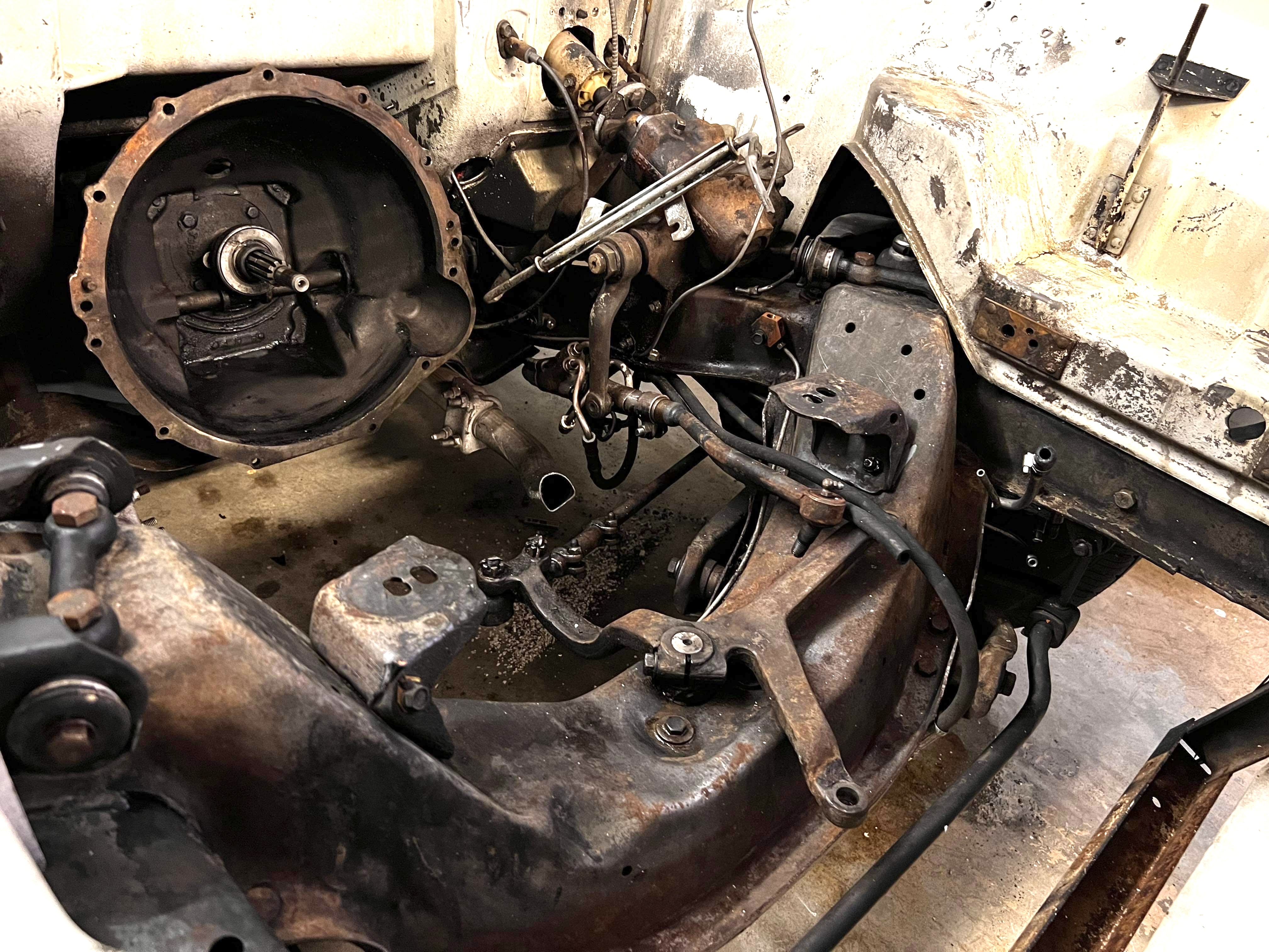
ELECTRICAL
There's no polite way to say this, so getting straight to it: This car needs to be re-wired. The underhood harness was held together with yellow crimp connectors and household wiring nuts. The battery cables were both dry-rotted and cracked through in spots. The power window wiring was broken at both doors. The old Prestolite voltage regulator was melted inside and its points welded shut. Somewhat forcing your hand here is that what was left of the harness has already been tossed in the trash like it deserved. Fortunately, the Avanti is an extremely simple car with extremely simple wiring.
Headlamp covers and gaskets are there and are in great shape. Included are a set of new Holley RetroBright seven-inch round LED headlamps in the 2700K "warm white" color temperature, so they don't look out of place on a vintage car. New front turn signal lenses (with chrome surrounds) are included. New rear taillamp lenses have been installed on the original taillamp housings, which are presentable but really do need to be re-chromed to be correct. There are also some stress fractures in the white metal that should be addressed. A new set of SI solid brass chrome-plated taillamp housings are included but I'm not happy with their fitment compared to the OE pieces. The rear backup lamp holders have been re-plated and look spectacular. Both rear brake lamp and backup bulbs are LED replacements.
The original antenna mast was snapped off and has been replaced with a new unit from Nostalgic.
The power window motors and regulators were hacked together from old Ford bits that were similar to but _not_ directly interchangeable with the Studebaker pieces. I've obtained new original power-window regulators and installed new power window motors from SI. The switches should be replaced as the originals switch plastic crumbled from age. I have the three new power window harnesses (passenger door, driver's door, and interior to engine bay) from a 1957 Ford Thunderbird, which is almost identical to the Studebaker harness and is properly color-coded, even.
A new blower fan motor is included.
The original starter has been restored fully (NOS armature, NOS field coils, NOS center support, new bushings, NOS brush plate, remanufactured drive) but it appears to be a starter from an automatic, which will bolt up and work but does not engage the ring gear as fully as the correct manual-transmission starter. A new Denso mini-starter is included, as only a masochist should want to reinstall the original Prestolite starter on this car.
The windshield wiper motor was sent off and is restored and re-plated. The wiring pigtail for the original connector, off the old body harness, has been kept.
The original dual-point distributor is included, Also included in a new aftermarket distributor that has been converted to remove the vacuum advance and lock the advance plate in place, and a proper MSD reluctor wheel, pickup, and adjustable-advance rotor has been installed, so that it would allow for a Holley Sniper EFI system to handle timing adjustments fully.
ENGINE
The engine is the correct serial number (RS1262) for the car and is removed and has been town down in advance of being rebuilt. It has never been rebuilt previously. The cylinder bores are still original-sized (there's a photo on the Google Drive of the measurements from the micrometer). When I received the car, the engine was filled with SAE 30 and what appeared to be a few bottles of STP for good measure. In addition to its mucus-like consistency, the oil was also dark gray and full of metallic sparkles. This poor engine was hurting for a rebuild but someone filled it with goo to make sure the oil light didn't come on for a propspective buyer. Say it with me: There's a lotta bastards out there.
Despite this, the bores should clean up fully with a .010" overbore. The coolant passages in the block are disgusting and the block absolutely must be gone over by a machine shop. The bottom frontmost head bolt o the passenger side was broken off at some point in the past and will need to be extracted. Someone covered it up by squeezing RTV into the hole and shoving the broken-off bolt head into the hole on top of it. There's a lotta...
The bearing shells for rods and mains were worn through to the copper substrate but the actual journals on the crankshaft look stunning and mic out to where nothing beyond a polish is needed, if even that. The timing gears look lovely and are wearing evenly.
An oil pump rebuild kit is included with new gears and shafts. The oil pickup was bent upwards like something had smashed in the pan at a point in the past and the screen, and only the pan was replaced. The pickup screen was mangled. It is still the correct pan with the correct baffling. It will need a new oil pickup if such a creature exists, or if a standard V8 pickup can be modified to fit.
The cam appears to be in great shape as well, without noticeable wear to the bearing races or lobes. Lifters and pushrods are likewise in decent shape and should be reusable. The rocker shafts appear to have suffered from a lack of oiling, probably because of the low oil pressure that caused the bearing wear and likely because there's no way the oil-goo in the enigne could fit through small passages. The ends of the rocker arms had deep indentations in them where they were not adjusted for a very long time and had been smashing into the tips of the valve stems. The shafts themselves had scuffing and galling where the rocker shafts were pivoting on them. Most of the adjusters were broken inside the rocker arm threads. I have a replacement set of rocker shafts with arms that are in significantly better shape and should be cleaned before installing.
The passenger-side exhaust manifold was cracked clean down the center of it, so a NOS manifold was purchased for it. A new exhaust riser valve is included, as is another manifold that does not have the riser valve, if you want to eliminate it.
A full stainless steel exhaust system with mounting kit and clamps from Nostalgic is included, along with new tips from SI.
The block is currently on a stand, which you get, as well as the cherrypicker and load balancer because I'd rather cut my own arm off than own another car that requires yanking the engine.
New mounts are included.
FRAME
Despite the car having been in at least two accidents before (see "body"), the frame appears to be very straight and clean. Hog troughs are remarkably straight and solid and do not appear to have been replaced. A NOS transmission crossmember has been installed since the old one was tweaked by somebody jacking up the car on it.
FRONT SUSPENSION AND STEERING
You're going to notice a theme here - the power steering sat so long with moisture in it that the components were trashed. The cast-iron pump body had been eaten way internally with rust. The control valve bores had gotten so pitted they wouldn't seal.
Because of its decrepit condition and the general awfulness of the PS system that Studebaker used in the first place, I decided to convert to manual steering instead. I have a correct OE arm for the Ross steering box and a new OE reach rod. The control valve was in such bad shape that after attempting to rebuild it, I pitched it in the trash. Ditto the pump. I still have a new set of all four hoses if you want to, I don't know, flagellate yourself with them to recreate the authentic Studebaker power-steering system experience.
The steering gear itself has been rebuilt with a new sector-shaft seal. It has not yet been filled with the semi-fluid grease crap it requires but a new tube from SI is included.
The center pivot has been rebuilt with a new bushing and bearing. End play has been adjusted and it has been filled with new grease.
The actual front suspension is currently disassembled. Mounted on the car are four new NOS control arms with new bushings and all-new mounting hardware. The end cap washers have been stripped and re-plated. Both king pins were heavily worn and have been replaced with brand new NOS (not rebuilt) pins. Needle and thrust bearings and zerks are new, and stainless steel cotter pins were used to lock in the trunnions. A complete new set of upper and lower pins and caps is included. I encountered an issue with the control arms where the bores that the caps thread into are not the correct size, and that was the moment I realized that I stopped having fun with this car about twelve months ago and now it's just annoying me. The rear suspension is in place and the car will roll if you dolly the front, or I can assemble the front enough to make it a roller, but I'd recommend dollying since that way you don't have risk damaging any new parts just to get it on a trailer.
Sway bar bushings, both for the bar and for the early-style extensions that mount to the frame, are new.
New shocks and mounting hardware are also included but aren't installed yet. The springs are cleaned and painted and ready to install. I'm including an absolutely fantastic spring compressor tool from a W124 Mercedes that fits in the middle of the spring and compresses it through the hole in the lower control arm. Don't take your life in your hands using the service manual procedure with the chain and the floor jack.
GASOLINE
The 3507S carburetor has been rebuilt with a kit from Nostalgic, including the proper accelerator pump for an R2. The primary and secondary shaft bores in the carb body were very worn and were bushed during rebuild. The primary shaft is a new aftermarket piece since the linkage bracket had wallered out on the end of the original shaft. All linkages and brackets have been stripped and re-plated and a correct date-coded repro Carter tag was added to the rear of the carb. The rebuild also included new metering rods, springs, and shuttles, and primary and secondary jets. All holes were chased (not tapped) prior to reassembly. New needles with viton tips and seats were installed, and the floats cleaned, checked, and adjusted. When it was disassembled, the carb had an eighth-inch of rusty silt in both float bowls from rust in the fuel system. We'll get to that in a second.
The fuel system was chock full of water (surprised?) from sitting with old gas in the tank. The bottom of the original tank was rusted enough that it didn't warrant saving, so a new aluminum tank was installed. At the same time, the vapor loop was replaced in the C pillar. A new gauge sender was installed. The filler neck was rusted to here and back as well, so it was removed, stripped to bare metal, and re-plated. A new gasket for the filler neck as well as the rubber filler neck tube were installed. A new cap rounds out the rear fuel system.
The old fuel lines were removed. A full new set of pre-bent stainless lines - supply and return - is included, as well as a mild steel pre-bent supply line that I ordered before realizing my mistake.
The fuel pump was pretty well destroyed internally on account of the rust granules that were being sent through it, so it was rebuilt with a kit. I didn't like the quality of the check valves on the kit, so I bought a NOS Carter center section for an AMC 258 straight-six, which had new "hats" and springs, and used those in addition with the new rubber valve flats.
A "S-P" branded new fuel filter is included.
The supercharger is painted black and had a sticker on it stating that it was rebuilt by "Herndon Studebaker" in Madera, CA, but I can't find anything on that name through Google, so Lord knows its age or provenance. It does turn freely and smoothly and appears to have ATF in it.
PROPELLER SHAFT AND UNIVERSAL JOINTS
The prop shaft appears to be straight and balanced. I've stripped and repainted it. Two new U-joints with bearings are included, as well as new Spicer-branded bearing straps for the rear differential. A new front yoke will be needed (see "Transmission")
REAR SUSPENSION AND REAR AXLE
Hey, guess what happened to the rear axle from sitting? Did you guess "water-induced rust damage"? Shocker, I know.
The rear axle is a Twin Traction unit with a 3.73 ratio that was pretty well knackered from rust damage. The axle was stripped down to an empty shell, cleaned, and repainted. The Twin Traction unit was rebuilt with new clutch discs, new bearings and races, new torque buttons, and a new roll pin to hold them together so they don't fall out. The ring and pinion appeared to be wearing well, so those were reused. The axle tubes were cleaned out with a flex-hone to remove rust damage. The tapered axles were retained, but given new outer bearings (which were packed) and races, and were adjusted per the manual on the passenger side of the axle. Gaskets to seal against the backing plates are new.
Rear sway bar bushings are new, and all hardware has either been repainted or re-plated. The rear sway bar brackets are also new, as the originals were smushed like someone once tried to jack up the car by lifting on them.
Rear shocks and hardware are new, too.
TRANSMISSION
Oh, boy. Here we go.
The original four-speed transmission was destroyed by the stupidest hack fix I've ever seen, and that's saying something. Due to some damage, maybe the same damage that caused the oil pump issue, the rear mounting bosses on the transmission were broken off. To fix that, someone cut a 1/4" thick piece of steel to cover the hole in the center console from inside the car, and welded the Avanti shifter to that from underneath.
If you're asking how that worked, with the shifter mounted to the car body and the shift rods attached to a moving transmission, the answer is "not great".
The shifter being misaligned led to a lot (and I do mean a lot) of internal damage. The shift forks were worn down to points. The dogteeth on the synchronizers, the gears themselves, and the slider hubs were chewed to bits. The reverse idler was worn down to nubs. Metal got into the ball bearings so they turned with a chunky action. The teeth on the speedometer gear were pitted and broken. It was a hot mess.
A rebuilt Studebaker transmission was found two hours south of Seattle in Vancouver and procured, which had all new synchros, bearings, new torque-lock sliders, new thrust washers, and a completely new mainshaft. The only problem is that it used the early GM-style bellhousing pattern instead of the Ford-style bellhousing pattern on the Avanti. Fortunately, the old transmission case was still good — everything bolted to it, not so much — so it was refurbished and the guts and tailshaft from the new transmission were swapped into it.
I think we can agree that locating a shifter bracket for a four-speed Avanti is just about impossible, so the path of least resistance was to go with an aftermarket Hurst setup, so a 373-3157 installation kit and 391-5403 shifter, with a 332-7302 steel bushing pack, were installed.
The Hurst rods that come with the 373-3157 kit would not work for reverse - it needed a reverse arm that would drop the linkage about 1/2" to really have the right angle - so a 105-2142 reverse arm was added that fixed the angle of the reverse linkage.
The only outstanding issues with the transmission are:
• It needs an early T-10 reverse switch bracket. A new switch and reverse linkage are included, but it needs to be mounted to the transmission and connected to the reverse arm.
• I currently have a plug in the transmission where the speedometer cable should go. A new speedometer cable is included but it will need the gear that mates to the helical gear on the input shaft. The one that was removed was unusable.
• The new mainshaft has a 27-spline output and it will need a new yoke that mates to the bearing size on the U-joints.
The bellhousing is not refinished yet and could use some attention; it's very oily and ugly compared to everything else.
WHEELS AND TIRES
The original Avanti hubcaps are there, but someone has painted the centers of them black. They will need to be refinished. The original wheels were painted red at some point by someone who will probably stand in judgment for doing so after they die.
I had the four original wheels powdercoated silver metallic and four new BF Goodrich Goldline 205/75R15 tires installed. They are fitted with chrome trim rings and have NOS Studebaker dogdish hubcaps with red centers. The spare tire was missing, so a new reproduction Studebaker wheel was sourced and a 670-15 Firestone pie-plate bias tire installed on it.
Sale also includes a full set of 15x7 magnesium Campagnolo wheels from a DeTomaso Pantera, along with new center caps and retaining clips. I bought them on a lark since I thought they may look interesting on an Avanti.
BODY
- All glass is in good condition and present
- Someone really monkeyed around with the quarter windows in the past. They were installed with plumbing dope and most of the little brackets that were supposed to hold the mounting screws were ripped out or the fiberglass broken out
- The passenger door is disassembled because the inner shell was a mess of stress cracks. All of them were ground out and filled with marine fiberglass repair resin, then sanded out and painted
- The leading edge of the hood is beginning to crack where the hinges attach, which is pretty common on Avantis
- I can see at least two previous damage repairs on this car - the passenger side door sill and the driver side front turn signal bucket have both been repaired in the past
- This is an early hood with the center support brace
- The spare tire lid was made from a piece of masonite when I got the car. I've replaced it with the correct plywood in the correct shape. Both the latch and the bracket on the body were missing and I've NOS pieces from Nostalgic that need to be installed.
Interior-wise, included are a new dash pad from SI, a NOS climate center console panel (in fawn) from Nostalgic, a NOS gauge surround bezel from Nostalgic, a repro overhead switch panel from SI (the one in the car has some age cracks), and a full set of new Stewart-Warner gauges for the cluster from Nostalgic, as I was going to send the originals off to be restored properly and planned to use those in their stead.
The rear seat frame was extremely rusty, so it was cleaned and the seat rebuilt with freshly-steamed foam, new burlap, and stainless steel hogrings. The front seats appear to be in great shape with no rips or tears. The headliner appears to be a replacement hard-plastic piece that mimics the look of the original vinyl.
THE FUNNY
I want this car gone. I can't stress enough how much I don't care about it, and how much I resent its presence, and how badly I want the space it's taking up back so that I can park my new iX in the garage.
I can't promise you that every piece and every part is there to make a complete Avanti; I believe it to be complete but you know how that goes. That said, if you were ever a fan of LEGO sets as a child and enjoy building your own fun, maybe this is for you.
The title is clean and clear and in my name. You'll need a flatbed for the car and a large enclosed trailer or a van for the rest.
Here's a little light viewing for you: https://drive.google.com/drive/folders/1r6M4-b__hz-edvPo6cD8zAJESQ1osjae?usp=sharing
RECEIPTS
https://drive.google.com/drive/u/1/folders/1QFvKfw8mVgdFzeN3CoJsEzM7vnYhq-9k Everything listed is either installed or included in the sale. The SI, Avanti Parts, Coker, and Nostalgic contain the lion's share of items. Ellingson is the bill of sale.
PICTURES
https://drive.google.com/drive/folders/1rXxX7ICktTAaHWY9Lr7EodEi4OL80kyT?usp=sharing
Located in Kirkland, WA