


grobb284
-
Posts
185 -
Joined
-
Last visited
Content Type
Profiles
Forums
Events
Posts posted by grobb284
-
-
I found some magnesium wheels that have a distant similarity to the Avanti wheel cover.
Here is a photo of the original Avanti wheel cover I took from Ebay.

I have to agree with Tom (SBC96), his Mustang Cobra wheels probably look the closest. Especially with the defined edge of the concave center on his wheel .

Well I know it's a stretch, but these magnesium wheels look a distant cousin to the Avanti hubcap.
I'm hoping to run 18 x 9 1/2 on the rear, 17 x 8 1/2 on the front. Should look proportional with 255/45/18 rear tires, and 235/50/17 front. This should be a 27 inch tire rear, and 26 3/8 front.
The car is on jack stands, the fender to wheel gap will be reduced when on the ground.
I'm trusting that my friends both on the internet and here at home will help in designing a superb Stude logo for the center caps. For those that want to get started, they will be approximately 2 5/8" in diameter.

For those that might think any 5 spoke would look similar, here are the 5 spoke aluminum that I was originally going to use, and they don't look anything like the Avanti wheel covers.

-
David,
Sorry, I have nothing to add to your question on steering boxes.
I just wanted to say that I really was impressed with the photos of your work taken at a recent chapter meet that they posted on the internet.
Keep up the good work.
Best regards,
Gene
-
Just found this on Ebay, is this it? For 1996 to 1999 Ford Taurus.

That would fit the part number, perhaps.
-
SAE AP2 96TS L (for left)
SAE AP2 96TS R (for right)
Years ago, a number on the lens indicated the first model year of manufacture. Do manufacturers still do this?
If it is from Ford, would it be 02 or 96?
-
Curious where this front side marker light came from on the Avanti's built from Firebirds. Is it from the Firebird?

-
I have several questions regarding hog trough replacement; they are,
1) excluding the benefit of stainless "lasting a lifetime", what are the pros & cons of one-piece vs three-piece troughs?
The three piece are probably easier to slip under the car, as well as ship. Have not used the single piece ones.
2) are three-piece troughs welded, screwed, or riveted together once in-place?
Yes, to all three.
The long pieces are riveted together, the front piece is bolted to the rear and then welded together if you wish.
3) how "exposed" are the rivets that secure the replacement troughs to the rocker panels?
You may wish to caulk the lower rocker to the trough lip, rather than rivet. If you rivet through, you may wish to do some bodywork.
4) I read an early description of someone replacing hog troughs and he talked about needing 40 hours to replace the troughs - how realistic is this time?
It may have been realistic for him. For us, it took a good bit longer, so as not to make a mistake and damage anything.
We did an iniitial design of a replacement strengthening assembly instead of the hog troughs and gave to Phil Harris at Fairborn Studebaker. The hog trough removal would be the same time. The installation would be probably less than 1/3 the time as hog troughs. Should be less expensive as the hog troughs, if Phil decides to develop them. By the way, I've got nothing involved in this; gave the drawing to Phil as a courtesy for all his help.
-
Joe:
Was over at Fairborn Studebaker yesterday, visiting Phil Harris for some supercharger parts. He was kind enough to take us to lunch in his Avanti. We measured in his trunk when we got back. Looks as though we'll have an inch clearance.
Thanks again for your help.
Best regards.
-
Joe:
Thanks for the photos. It appears that our electrical enclosure may not be any farther forward than the actual hinge bracket that secures to the fiberglass.

I have circled your photo to show where we think it will be. Can you give me a dimension under this metal part of the hinge if it is different than the 10 1/2 you mentioned?

This view is from the rear window opening taken from the passenger side, looking back into the trunk. This isn't a great perspective, but the enclosure will probably be just under the immovable metal part of the hinge.
Looking forward to hearing from you.
Gunslinger:
Thanks for the input, we're trying to reduce the clutter within the engine compartment. The spot you mentioned would be a very practical location. Thanks.
-
Recently working on an SN93 Paxton Supercharger. The front housing had cracks in the deep conterbores for the six 3/8-16 SHCS that draw the whole assembly together.
In contacting Paradise Wheels, no new housings are currently available for SN93's, and this is a common problem.
We found an acceptable solution was to convert to hex head screws, and seal the shanks of the bolts with O-rings in the counterbores. Here is a photo of the completed assembly.

Here is link to some photos of other Paxton superchargers completed, VS57 and SN60, as well as SN93:
-
PaceRacer50 of the Studebaker Racing forum suggested that I place the fuse panel in the trunk of the Avanti. It was a good suggestion and we went with it.
The best unused space was behind the drivers side rear wheel well. However, it would have not been easy to work on it sideways in the trunk.
Recently made a swing arm that rotates the fuse/relay panel enclosure from behind the driver's rear wheel. It moves it out to a more accessible position for servicing and making wiring changes. No more laying contorted under a dash.

This is the stainless enclosure, swing arm, and bearing assembly.

The swing arm bearing assembly fits in the left rear body mount cavity.

The electrical enclosure to placed in the normal position, right behind the wheel well.

The electrical enclosure in the servicing position. I don't plan on closing the trunk when the enclosure is in this position, but can someone advise me if the hinges would clear? I may forget sometime.


-
I could use the Avanti tank.
Sorry can't help with the pictures, the only MAC I Know how to use has "BIG" in front of it.
Sorry for the terrible joke.
Looking forward to your photos.
Best regards,
Gene
-
David,
That is good advice to contact him. He would know.
How about sending me some update photos on your project. Or better yet, post some here on the forum, I'm sure others are interested.
Do you still have your fuel tank, for those of us still using oil based propellants?
-
Been working on making an Avanti wiring schematic with more up-to-date fusing. (Object: NO electrical fires in a fiberglass car)
Have just about finished all the lighting system. In doing the header panel, instead of using two rocker switches to control a given function, I've considered doing this:
I've been thinking of upgrading to some new rocker switches. Planning on using one rocker to replace each group of two, using a three position rocker switch. Characteristics being On-Off-On.
This would permit more controls on the header switch panel. One of the rocker switches I'm looking at in addition to being a three way, also has integral LED's for the two "on" positions, a "plus".
Conversion of existing type control from two switches each to one switch each:
Heater blower: High-Off-Low
Instrument lamps: High-Off-Low
Headlights: Headlights-Off-Park
Some additional rocker switch controls could be:
Radiator cooling fan: High-Off-Low
Ignition: On-Off-Accesories, with a PB starter button.
Emergency flashers: ON-Off, (two position switch)
What I'm looking for are some other automotive functions that would naturally go into this header panel. Any suggestions?
-
Some photos taken while we had the stainless Avanti frame and the body on the car lift.
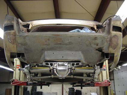
Rear view of Avanti with Viper differential with Corvette suspension, on the car lift.
The cut outs in the rear body pan were made at the factory to fit up the later model Kevlar bumpers
If anyone has any pieces of a rear body pan that has been wrecked, we would like to use pieces of them to eliminate the "shackle boxes" and continue the smooth curve to the rear quarters.
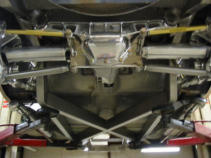
Bottom view of Avanti with Viper differential with Corvette suspension, on the car lift.
The floor tunnel for the drive shaft is close, may have to be raised.
You can see the substantial x-member of the stainless steel frame.

Front view of Avanti with Viper differential with Corvette suspension, on the car lift.
The items circled in red are the gas tank mount reinforcements of the body, which the notched frame clears.
The items circled in purple are pressboard that has been secured to the inside of the body to act as a backup to filler placed where the rear bumper side mounts were. This also was done at the factory for the Kevlar bumper modeling.
-

Front firewall of the fiberglass Avanti body on the stainless steel frame.

This is a closeup of the body mount at the firewall of the Avanti, on the stainless steel frame.
The rivets in question are circled in red. Are these rivets a structural part of the fiberglass mount, or were they just used to secure the fiberglass mount to the body until the resin cured? In other words, can these rivets now be removed with out any loss in structural integrity?

This is a closeup of the driver's side inner fender where it meets the radiator support.
The rivets in question are circled in red. Again, can these be removed without any loss of structural integrity?
Thanks in advance for the response.
-
A long range goal would be to replace the steel frame, if possible, with an aluminum frame if the weight reduction would be significant. Are you saying the aluminum I-beams you have could be used to replace the X-member in the steel frame and if so, any guess how much weight would be saved?
If you are interested I have some web pages which are slowly being added to:
http://www.nbeaa.org/new_jan_07/heacock/heacock.htm
Dave
Dave:
Very impressed with your progress. The speed which you are accomplishing things is very good, don't be so hard on yourself.
Typically aluminum is 1/3 the weight of steel, but 1/2 the strength. I was proposing an all aluminum chassis with the aluminum I-beams making the x-member. To have the frame near the same strength, probably a 1/3 savings in weight. If you decided you would not need it as strong, perhaps a greater savings in weight.
Incidentally, stainless is perhaps 30% stronger than mild steel. A similar savings in weight could be found if we reduced the wall thickness of the tubing to correspond with the original strength of the tubing in mild steel.
I like the idea of either stainless or aluminum, aluminum is just a little more difficult to weld, and the welds never look as good.
I have seen numerous weights assigned to the original frame. We weighed one utilizing two scales, one at each end of the frame, was well over 300#, however we found out later that the scales may have been damaged. It still had the clutch linkage, as well as the rear shackles, and part of the front of the rear leaf springs where they had been cut off with a torch. Solanki weighed one and came up with 250#. Our stainless frame came in under 250#. Our X-member was lighter, and the front frame cradle construction was lighter, but I don't know what the original frame actually weighs. We will try and weigh it again when we remove if from the Avanti body that it is now under.
Best regards as always.
-
Would this design work as an aluminum frame? Did this eliminate the need for the torque boxes?
Dave,
1.This may work for an aluminum frame. May require some changes in the tubing dimensions. I have some nice looking aluminum 6061-t6 I-beams that could work well for the X-member.
 They would approximate the original Studebaker steel welded I-beams for the X-member.
2. So far this has eliminated the hog troughs (Torque boxes). By the way, just about have the drawings ready for production of a hog trough elimination on the original Studebaker Avanti frames. Should take perhaps 1/4 the time for installation of normal hog troughs, and looks pretty decent under the car too.
-
Just finished this recently:
*Drilling the two rear body mounts to match the roll bar.
*Drilling the two side body mounts to secure the floor pan at the front seats.
*Fabricated the two body mounts at the firewall.
*Shimmed all the body mounts to the floor pan.
*Bolted all the body mounts to the roll bar, floor pan, and firewall.
After checking all the mounts for squareness to frame and being level, tacking them to the frame.
We then removed the body from the frame, and prepped the frame for TIG welding the body mounts.
Assembled the side pipes, and installed the silicon grommets for noise and heat isolation.


-
[Gene, that is the piece that is behind the fiberglass behind the door strikers. When you bolt down the door striker with the phillips screws, you are screwing the screw into that backing plate. The slots in there are for the retainer behind the fiberglass. As far as the body tag, one of my R3's has the same narrow tag. I don't know when they started using it or discontinued using it. I can send you pictures if you want.
Nimesh
Nimesh:
Thanks for the response, I had no idea what that piece was.
Just curious, what is your body number on the narrow tag?
Best regards as always,
Gene
-
What in the world is this? The six inch scale is to give a reference to size.

This was covering the heads of the two bolts retaining the roll bar to the hog trough on the drivers side. This would be inside the rear armrest, just over the hog trough.
They were over the bolt heads, I couldn't tell if it was tack welded over them, or just tightly wedged and rusted. It took a slide hammer to pop it off.
Amazed that it was there, what ever it is.
-
The Avanti body tags that I remember were a larger rectangular plate. This narrow tag is on a low number body, was this the normal body tag? When did they change?

-
Glad you and Peter are conversing, should save duplication of effort in engineering.
On the Corvette rear end I want to use coil overs rather than the fiber spring so I can pick the coils after I can figure the final weight of the vehicle. Since I have never done any of this before I'm sort of going by what others have talked about. The tie rods(?), I think we are talking about the same thing, can be modified so they attach from the bottom rather than over the top--again I haven't done this yet and and all my paper work is at home so I'm just trying to remember some of this.
I have adapters to convert the rear tie rod mounts from taper to straight for reverse mounting of the tie rod at the knuckle. I also have mounts at the knuckle for for the coil overs that move them out for coil clearance to the half shafts.
I have been thinking of cutting out the spare tire well and making a square hole so I can install batteries which can be placed lower than the bottom of the well but no lower than say where the exhaust was to begin with. This will help balance the weight front and rear and lower the center of gravity of the car.
If I remember correctly the wheel to wheel mounting surface is about 65 or 66 inches? I have had the half shafts shortened but nothing is back together yet. I need to go back and see what we are talking about clearance of knuckles and cover mount? but I think I have looked into this and it should be okay.
Avanti 58-58 1/2, early C4 62 1/2, later C4 63 1/2 +.
You have been lots of help. I'm thinking once I get the rolling frame I will place it under the body and slowly lower it to see where I need to make the cuts. Does that sound like a plan?
Yes, it sounds good.
Dave
-
This really looks nice and the completed car should be great. With my modification to my 85 by installing the Corvette rear end I have been wondering how much of a modification I need to make at the rear end. Did you have to make any other cuts in the rear within the passenger area or was the only cut necessary the removal of the spare tire well removal? By removing the spare tire well does this have any effect on the overall strength or stability of the body? Any pictures of the underside of the body attachment points?
Looks great, Dave
David:
I recently spoke with another gentleman interested in electrifying his Avanti, did he contact you?
Cuts had to be made for the leading edge of the 4 links.
The spare tire well was removed only to view the rear end. With as many body mounts we have, no strength loss from its removal. The Viper rear end and its attachments clear the spare tire well. I doubt you'll find that to be the case with the Corvette, the spring perch and the tie rods in particular.
When you narrow the rear axles and tie rods, will the knuckles clear the cast rear rear cover mount? It's perhaps 8-10" wider than the Viper's. Have you established the wheel to wheel mounting width?
Let me know if I can be of assistance.
David, here is a more recent photo and a link to more.

-
Here are some recent photos of the body on the stainless steel Avanti frame.
The following have taken place:
a. Body (floor pan) modified in those areas necessary for clearance. These consist of clearance for the 4-link, the Viper rear mount, and the front kick up.
b. First paint stripping of the body
c. Some Corvette tires and wheels installed temporarily. These are 275-40-18 rear, 245-45-17 front. We are contemplating 255-50-17 rear, 235-50-17 front, or something close, in those areas.
d. Body aligned to wheels.
e. Side pipes checked for fit.
If you look for the side pipes, you can see them. They are unobtrusive by being under the rocker, rather than outside. If you stand near the body they are hidden, and can been seen at a distance. The turn out tip in front of the rear tire in the re-entry wheel well looks like it was made for it.


Studebaker Avanti Magnesium wheels?
in Avanti Pub
Posted
Dave,
Those are Corvette magnesium wheels, optional from 1999 to approximately 2004. They are inexpensive used, for the paint chips easily, and are almost always chipped.
I think that Speedline in Italy made them for GM. There may be some aftermarket copies of them in different sizes, I don't really know.
I'm looking at installing an Aisin AY6 manual 6 speed transmission right now. The concept is to install the Cadilllac 3.6l twin OHC V6. They rev to 7,000!
Of course this is always subject to change. I've got the transmission, but having difficulty finding a manual shifter from a CTS.
I'm going to raise the transmission tunnel a little, I want more ground clearance for the transmission.
The gas tank you supplied looks great on the outside. I've not removed the sender to look inside yet.
Your pictures of your project you sent are encouraging, keep up the good work.
Best regards.
Some photos of the transmission being fitted.